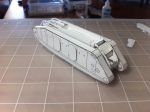
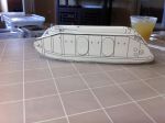
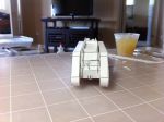
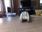
Landships II

Members Login
Username 
 
Password 
    Remember Me  
Post Info TOPIC: 1/72 Cardmodel MkIX "Pig"


Colonel

Status: Offline
Posts: 206
Date:
1/72 Cardmodel MkIX "Pig"
Permalink   


the MkIX was based on a set of drawings from Tankette, but using the track fame profile from the older drawing that appears in Fletcher's books.  This still a work in progress, only the 3D models for now.


Attachments
__________________


Legend

Status: Offline
Posts: 1062
Date:
Permalink   

I'm inclined to think (after a quick perusal of the photos in the Landships II article) that neither drawing gets it quite right: there should be a noticeable kink upwards in the lower track run towards the rear of the vehicle, and the curvature upwards to either side of the track contact patch looks exaggerated in both drawings - one of the pics (http://www.landships.info/landships/tank_articles/images/mk_9_2.jpg) suggests only subtle curvature along most of the length of the vehicle, with the significant points being the upward kink below the drive gear bearing caps at the rear, and around the second vertical plate-joining strap at the front (just a strengthening of the curve, not a kink).

Other photos in a book (The Complete Guide to Tanks & Armoured Fighting Vehicles, George Forty and Jack Livesey, Hermes House, 2006, p.397) showing the Bovington MkIX in its old location outside, suggest that the Wilkes drawing may be correct in showing a greater rise behind the contact patch than in front of it, but the rise in the drawing is still too great.

As for CG, the Wilkes drawing (the external view) is more accurate: the photos in the aforementioned book show the Bovington Mk IX resting on the ground (where the left track rollers are missing/collapsed?) from around the eighth track roller at the front (counting from the front) to around the nineteenth at the back. The Wilkes drawing seems about right for the front contact point, but the rear one needs to be moved backwards towards the rear edge of the second side door, which is roughly at the nineteenth track roller.

Try this landships drawing for a decent estimation of the Cg/contact patch.


-- Edited by TinCanTadpole on Tuesday 30th of October 2012 01:54:05 AM

__________________


Legend

Status: Offline
Posts: 1062
Date:
Permalink   

Yes, tightening that upper radius would be good.

As for the rise of the rear part of the lower track, although it's not very obvious in the side photo you've found, there is a kink at the last vertical plate-joining strap (near the bearing caps for the drive gears) where the rise changes from mild to more noticeable; if you add that in, it will lower much of the rear of the track whilst maintaining the height of the drive sprocket - assuming the drawing had it correct! So far as I can tell it is a rounded kink at one point that is required, rather than a smooth curve over the whole section. See here for the smoothed kink below the last join between side plates.


-- Edited by TinCanTadpole on Tuesday 30th of October 2012 04:06:11 AM

__________________


Lieutenant-Colonel

Status: Offline
Posts: 179
Date:
Permalink   

This looks very promising. May I askhow much discrepancy is there between the Tankette interpretation and the older drawing?

__________________


Colonel

Status: Offline
Posts: 206
Date:
Permalink   

the Tankette drawing is "signed" by J.P Wilkes, 1975.  The "a" drawing is from the Fletcher book and is a common one.

The most significant difference is the cener of gravity of the vehicle.  The Wilkes drawing shows it much further to the rear than the older drawing.


Attachments
__________________


Colonel

Status: Offline
Posts: 206
Date:
Permalink   

oops!  i got that backwards...Wilkes shows the CG further forward.


__________________


Colonel

Status: Offline
Posts: 206
Date:
Permalink   

agreed.  starting over, I began with the dimensions from the old drawing, figuring someone went to some trouble to get measurements down to the eight of an inch, do there is a good chance that they are accurate (unless someone wants to go measure the real thin for me.  I used the radii of the front idler and rear drive wheel from the old dwg.  Then I "connected the dots.  For the lower front track run I ran a spline between the contact length as you suggested (8th to 18 wheels) to the front idler.  The heavy red line in the upper profile is the result.

I found a good, almost square-on side photo, ran it through PaintShop Pro to take out as much of the parallax as I could.  I overlaid the same red profile, but with thinner weight.  Pretty good match except that the lower rear track run is still too high and the upper rear run has too much curvature.  I could take out most of the bottom difference by using a spline so I get a gentle curve instead of a straight line.  I can tighten up the radius for the top rear "corner" where the two upper rollers/idlers are.

comments?


Attachments
__________________


Lieutenant-Colonel

Status: Offline
Posts: 179
Date:
Permalink   

Thank you for the enlightenment! I am hoping to arrange a visit to Bovington at some time next year, and I have a list of dimensions to obtain if possible. I do wonder if Helen, who has done so much work to provide definitive drawings of a Mk 1, may be prevailed upon to extend her abilities to other subjects, or whether anyone else may have done some of the work without yet making it available.

Meanwhile, the current interpretation is looking very promising. Keep up the good work!

__________________


Colonel

Status: Offline
Posts: 206
Date:
Permalink   

Thanks for the input. 

Field measurements of the real article are always beneficial, but I will likely get too far into this model before we get any more than we have already.

I sometimes have to remind myself that I am designing something that will be cut out of paper or card with scissors or a craft knife, then glued together by sometimes arthritic fingers.  Excellence in this case is what creates the correct "feel".  Perfection ain't gonna happen.  I have caught myself spending too much time on minor parts that don't justify the effort. 

I'll try to find time this evening to adjust the track profile as discussed above, and put up the hull profile screen shots for discussion as well.  I have found a lot of really helpful photos on the web, that take some of the guesswork out of interpreting the line drawings.  I want to get general aggreement amongst us before I start "exploding" the 3D model to make the individual parts.  I don't like doing the rivets more than once.


__________________


Colonel

Status: Offline
Posts: 206
Date:
Permalink   

OK, this is the profile adjusted as discussed.  Also a side view showing the revised track profile and the hull profile.


Attachments
__________________


Legend

Status: Offline
Posts: 1062
Date:
Permalink   

I thought I saw something to nitpick over in the curve under the front track horn, but having looked at photos carefully I think you've now got the profile just right, front and rear.

Whilst it's on my mind, may I suggest (though it's early for such things) a version with flotation drums and a "bridge" screen, as tested at the end of the war?

__________________


Colonel

Status: Offline
Posts: 206
Date:
Permalink   

Tthe flotation tanks were simple cylinders if I recall correctly, on on each side.  Add some brackets and we're done, maybe.

While we're at it, what color schemes and markings?  One obvious choice is overall brown drab with IC 15 markings like the one at Bovington.  After that, we can have one for Plan 1919 with the W-R-W RAC flashes and one for the US to go with the MkVIII.  The drawing showing one in splotch camo seems a tad far-fetched (attached)..., but maybe? 


Attachments
__________________


Legend

Status: Offline
Posts: 1062
Date:
Permalink   

I saw that splotch camo online last night - the site was "ww1artwork.jexiste.fr": since it's a French site, perhaps the person who made the illustration was trying a hypothetical French colourscheme?

Just had a look at the video of the amphibious trial (on the Landships II article). There are no obvious markings on the machine, but there's a third flotation tank in front of the cab, possibly some form of controls or voice pipe inside the "bridge" on top of the cab, and an inexplicable vertical (metal?) sheet mounted on the front right track horn. I've also read somewhere that wooden paddles (hinged, I think) were added to the tracks to provide propulsion in the water.

Must query the design of the flotation drums, as they blocked the side doors!

__________________


Colonel

Status: Offline
Posts: 206
Date:
Permalink   

views of the revised 3D model, with revised track frames.


Attachments
__________________


Legend

Status: Offline
Posts: 1062
Date:
Permalink   

Spiffing!

__________________


Colonel

Status: Offline
Posts: 206
Date:
Permalink   

I just watched the video on Youtube.  The panel on the right horn is certainly a mystery.  I would have expected one on both horns if it were necessary on one.

Emergency egress would have been a dicey business at best, and I don't imagine the vehicles were intended to be watertight to begin with.  That leaves the hatch on the cab and the one near the rear.  I'm going to watch the video more later to see if I can get some idea how the tanks were attached.  The braces had to be fairly sturdy, considering the weight they carried.

I plan to add alternate (and conjectural) front doors incorporating MG ball mounts much like the Medium B and MkVIII.  I suspect the need for lateral firepower would be keenly felt almost immediately, and the side positions would be the logical places to put them.

I am starting the first beta build now.  Pics later.


__________________


Colonel

Status: Offline
Posts: 206
Date:
Permalink   

Side-frame assembly pix.  0653 shows the stiffeners (ribs) attached to one side.  0654 shows the two sides with ribs between.  I considered spacing the ribs so as to miss the doors, in case someone wanted to open the doors to show the inside.  This might be possible, but it would complicate the rib layout.  Anyone competent to model the interior could certainly re-arrange the ribs to suit.  Comments, anyone?


Attachments
__________________


Lieutenant-Colonel

Status: Offline
Posts: 179
Date:
Permalink   

This is looking really good. I am looking forward to the complete build. Well done! (Or indeed, "spiffing"!)

__________________


Hero

Status: Offline
Posts: 870
Date:
Permalink   

I think the "mystery" panel on the right track-horn is in fact a tube for the air-intake of the radiator which can be seen earlier in PDA's video
Paul

__________________

 The finest stories of the Great War are those that will never be told.


Colonel

Status: Offline
Posts: 206
Date:
Permalink   

It would sure be in the right place and the engine would need the intake.  By George, I think you've got it!


__________________


Legend

Status: Offline
Posts: 1062
Date:
Permalink   

I'm in agreement - shame the video cuts out just as the vehicle is getting nearer the camera when emerging from the water, though. Looks like a rectangular section of trunking, then.

__________________


Colonel

Status: Offline
Posts: 206
Date:
Permalink   

More beta pix.  The files are large, so I'll upload them in two sets.

I haven't found any major problems.  The biggest one so far is the need to cut the tracks differently; The top rear run ends at the curve near the drive wheel, and I need to move it away from the curve so it can be glued down more effectively.  Not a problem, I think.


Attachments
__________________


Colonel

Status: Offline
Posts: 206
Date:
Permalink   

the rest of the pix...

662 shows the problem with the track termination near the drive wheel. 

The hardest part, I think, is going to be the rails.  I'll take a whack at that next.  Am I correct in assuming the MkIX was intended to carry an unditching beam?  It is roughly the same length as the MkVIII, which did not.


Attachments
__________________


Colonel

Status: Offline
Posts: 221
Date:
Permalink   

Wayne,

Can it be that there is something wrong with both sides of the tank (last picture)?? One part is more foreward than the other or is it just optical?

DJ


__________________


Colonel

Status: Offline
Posts: 206
Date:
Permalink   

They aren't attached yet, just three assemblies, sitting roughly side-by-side.

I want to add some of the details to the hull before I glue them together.  Then it will look more "normal"


__________________


Colonel

Status: Offline
Posts: 206
Date:
Permalink   

More beta-build photos.  666 through 670 are the completed beta model.

I'm adding rivets and other details now.  Instructions come next.


Attachments
__________________


Legend

Status: Offline
Posts: 1062
Date:
Permalink   

Aha! It never occurred to me that those panels between the roof and the overhead rails were a bigger version of the storage box on the Mk IV. The model looks good, btw.

__________________


Colonel

Status: Offline
Posts: 206
Date:
Permalink   

Model views with the tanks and one set with the tank supports only.  The tanks are segmented into six equal-length segments, presumably water-tight compartments.  a single compartment fits nicely at the front.  The logical places to support the tanks would be at the bulkheads and end plates, so seven supports per tank.  some of these would fall on the doors - not a good place to do this.  Other than that they seem pretty well located.  The configuration of the supports themselves are not evident from the video or the single still shot.  I plan to have a "strap" around the tank at the support, which could be the rib that appears in the photos.  Any ideas?

I will add the wave guard around the cupola and the air intake, as well as the "flaps" on the tracks.


Attachments
__________________


Legend

Status: Offline
Posts: 1062
Date:
Permalink   

Have just studied amphibious test video again; I make the following observations:

1) Front tank does not seem to project ahead of tracks, but is mounted further back and thus higher - it obscures the driver's view. Top edge of tank roughly at level of top of vision flap.

2) Seven segments per side tank, not six; the last segment may be slightly shorter than the others.

3) Stays are simple struts rather than shaped cradles; whether they are single struts or V-shaped is hard to tell given the graininess of the video, but they are angled slightly downwards toward the tank (the upper ones - the lower struts angle upwards) and do NOT make a tangent where they meet it. If V-struts are used, the twin ends join to the tanks and the single ends to the vehicle. Regarding fitting straps around the tanks, I think this would be inaccurate. The tanks seem just to have seam lines between the segments, and not all struts quite line up.

4) There's little or no gap between tanks and vehicle side. I think they rest against the side plating.

5) I agree more-or-less about the longitudinal positioning of the supports, but it looks to me as though there are larger gaps to pass the doors, with a single support between each pair of side doors. I count three struts before the first side door, at the segment seams, one halfway between the doors, then three more in the aft section.

6) Tanks should start about level with the second vertical plate-joining strap, immediately behind the radiator vent (which may, ideally need moving forward a little). The front tank is probably necessary as the side tanks start a little too far back to support the vehicle evenly.

Hope this helps!

PS - the last photo posted appears to show a curve underneath the front end of the conning tower/bridge structure, which does not exist on the vehicle in the video. A trick of the light in a grainy photograph, or were there actually two test vehicles, not one?


-- Edited by TinCanTadpole on Friday 16th of November 2012 06:53:23 PM

__________________


Colonel

Status: Offline
Posts: 206
Date:
Permalink   

I viewed the video aagain, too.  Not sure how I mis-counted the number of segments in the long tanks.

1. Front tank is indeed higher than the side tanks and does not protrude past the front horns.  This made me go back to the photos and re-scale the tank diameter.  I reduced it a bit, now.

2. sure enough, 7 segments per side tank.  It looks to me like the last segment is not significantly shorter than the others.

3. I have not been able to make out the brackets.  The left front one seems to me to be horizontal across the top, not slanting up or down.  As the vehicle approaches from the right, the dirt from the mud chute looks a bit like a bracket, but I interpret that as dirt only - I don't see the same slope elsewhere.  I cannot discern the brackets as struts.  Connection of single struts to a thin-walled tank would cry for some sort of reinforcement. 

4. I cannot see the space between tank and vehicle.  As close as possible makes sense.

5. When I moved the front of the tanks back as you suggest, and put in brackets at each segment, I had to move a few only a little bit in order to avoid the doors.  I cannot count the brackets betwen the doors.

6.  I agree with moving the the front of the tanks back behind the intake, so that the right one clears it

7.  The curve looks to me like a trick of lighting and poor film quality.

8. I suspect that little thought was given to how the tanks would be removed after use.  The more immediate problems would seem to be providing sufficient buoyancy, properly distributed to balane the weight, and the need to continuosly bail out the water tha got past the seals.

The views show the smaller tanks.  I'm still showing curved brackets for the time being.  Note the spacing on the right side only (I removed the brackets on the left side.).  The front tank is pretty snug against the nose plate.  The only way to get it closer would be to remove the tow hook bracket at the nose.  The bow MG would have to be unshipped or pointed at maximum elevation, maybe.  The MG was probably removed for this test anyway, so they could seal the opening.


Attachments
__________________


Legend

Status: Offline
Posts: 1062
Date:
Permalink   

Okay, viewing yet again I agree that there is little obvious difference in segment lengths and the struts seem closer to the horizontal. Part of my assessment was based on the video, part on one or two stills - which may well have given me a false impression because of the poor resolution.

Whether the brackets are curved supports as you have drawn, or struts as I suggested is indeed still a debatable point, as is the single bracket between the doors. The tank will be fairly thin-walled, but whether it's as flimsy as an oil drum or not is guesswork; certainly if bulkheads were located between each segment then that would considerably strengthen the mounting points for struts, and there surely must be bulkheads within the tanks to prevent any leak from flooding the entire tank.
I won't argue against your design of bracket, particularly given that you've closed up the gap to the hull sides (the space was on your drawing, not the actual vehicle).

The front tank looks much better in the new location, and indeed the bow MG is probably unnecessary, though I doubt the opening would be sealed up as it is at a similar height to the vision flap - which was open!
Whether or not you include the MGs, I suppose it depends whether you want to finish the model as the test vehicle, or in hypothetical "Plan 1919" colours. Either way, it's coming along nicely and a little adjustment of the segment lengths (equal?)/bracket positions should sort out a very interesting model.

__________________


Colonel

Status: Offline
Posts: 206
Date:
Permalink   

It is coming along, but very slowly.  Looking at the video yet again, I believe I can see "daylight" among the tank supports as it approaches from the right. A pair of "V" struts at or near each segment end would be very easy to model and not too difficult to construct.  I can add something similar for the front tank.

Do you get any sense of whether the raised screens were canvas, like the WW2 DD wading screens, or light sheet metal?

I interpret the two pipes that rise from inside the cupola screen as exhaust pipes.  Maybe they are attached outside the screen near the muffler?  I'll have to go back to the video...again.

As for colors, I was thinking khaki-brown for the vehicle and medium gray (gray primer) for the tanks and brackets.

In the meantime, I started a beta-build of the basic MkIX in Plan1919 colors.  I made the mistake of leaving the almost-finished model too near the floor.  One of our Scottish Terriers decided to taste it.  It now looks like a battle casualty.  Oh, well...I needed to make a few adjustments anyway.

I have three models so far: (1) white model, (2) Bovington, marked as the one at the museum, and (3) UK Plan1919.  Maybe we'll add US and French Plan1919 versions...beute version?.

Markings for the UK Plan1919 include the RAC flashes and an ID number.  Assuming MkIX's would be organized into batallions of 25 or so, to match the infantry organization, I could see maybe 8 batallions from the initial order of 200.  I assumed the batallions would be numbered so as to not cause confusion with the tank batallions.  The result - I used an ID of "8-20" for 20th vehicle in the 8th batallion.  The other thing I added might be equally debatable - additional MG's on the sides.  I included two extra "what-if" front side-doors that incorporate large MG ball mounts similar to those on the side doors of the MkVIII; the model can be built with or without them.  I expect that combat experience would have quickly shown the advisability of this, to provide covering fire as troops exited through the rear side-doors.  I considered an extended side door, like the Medium B, but concluded that overall vehicle width might have presented a problem with rail transport.  There are lots of possibilities here.  I am open to ideas on this.


__________________


Colonel

Status: Offline
Posts: 233
Date:
Permalink   

Hello,

Very interesting subject that I would like to see kitted in 1/72 !!!

All the very best

__________________

Eric

On going : Obice da 305/17 su affusto de Stefano, Mark 1 female ...

Finished : Dennis 3 tons lorry, Jeffery Poplavko, Renault EG, Renault FT


Legend

Status: Offline
Posts: 1062
Date:
Permalink   

The "bridge" screen looks like metal sheet to me.

Re MG positions in sides, the design has numerous loopholes already - presumably these were intended to be used for lateral cover, but you have a point in suggesting that experience might demand extra protection.

The two long pipes, which I've just noticed lie in line astern, do seem to be exhaust pipes; I think they're offset a little to the right, just like the silencers of Mk V tanks (which had the same engine). There's also another, short tube sticking up above the side or front of the screen: a speaking tube, perhaps?One would certainly be necessary to give orders to the unsighted driver.

__________________


Colonel

Status: Offline
Posts: 206
Date:
Permalink   

More views, now with the screens and pipes, and open brackets supporting the tanks.  The final model will delete the muffler and run the exhaust pipes directly from where the muffler is now.


Attachments
__________________


Legend

Status: Offline
Posts: 1062
Date:
Permalink   

So you reckon the third pipe is at the side of the screen? I wasn't sure if it goes there or at the centre front. In any case, the model is going to look fantastic.

Edit: on second thought, it couldn't really go at the front, because the front overhangs! smile


-- Edited by TinCanTadpole on Wednesday 21st of November 2012 11:43:52 PM

__________________


Colonel

Status: Offline
Posts: 206
Date:
Permalink   

I see four "pipes".  Two from the engine, one near the driver's cupola and a fourth one that looks like a support for the two exhaust pipes.


__________________


Legend

Status: Offline
Posts: 1062
Date:
Permalink   

I agree fully.

__________________


Colonel

Status: Offline
Posts: 206
Date:
Permalink   

Pix of the UK Plan1919 model.  I used the "what-if" side doors with added the MG's.  The model has a full set of the original doors, plus these two.


Attachments
__________________


Legend

Status: Offline
Posts: 1062
Date:
Permalink   

Overall, very good; the shape seems captured well and the stance looks good.

I'm not sure about the numbers though, it seems a little strange not using something along the lines of the "IC xx" markings, and I'd like to see the brown colour lightened towards tan.

The four digit number (1206) may be best left out, as that range of numbers would long since have passed (Mk IV tanks had four digit numbers starting 2 or 4, Mk Vs starting 9; Mk V*s had four digits starting 9 or five digits starting 10; Mk VIIIs had five digits starting 12, although not necessarily marked on the vehicle); If you want such numbers on the model, I suggest either five digits starting 12 at least, or perhaps more likely a shorter sequence of numbers preceded by a single letter - such as the "Axxx" numbers worn by Whippets (Bovington's Caesar II is A259).

If he looks at this thread at all, Gwyn would be the man to ask about these numbers.

__________________
1 2  >  Last»  | Page of 2  sorted by
Quick Reply

Please log in to post quick replies.

Tweet this page Post to Digg Post to Del.icio.us


Create your own FREE Forum
Report Abuse
Powered by ActiveBoard