You are probably aware that I have been posting improvements for the new MB Mk 1 tank steering� tail and that I have mentioned that some of the techniques apply to the Airfix unit.� Well in an idle moment I started modifying a spare Airfix tail and decided I should post the work for anyone to follow, well anyone who cannot obtain the Master Box offering anyway.� You will be aware of the many modifications required of the Airfix tank to create a Mk 1 - those modifications can be found elsewhere.
�
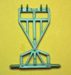
The tail unit can be modified reasonably easily, you will require a sharp knife/razor blade, some emery board/wet & dry, and some 2mm H section (Evergreen 282 H-column) or similar.� Failing that some 2mm square styrene for the replacement axle.
Stage one:
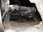
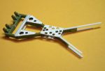
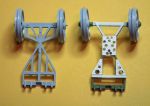
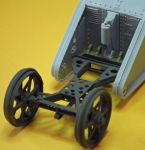
you need to remove a fair amount of plastic and slice through the axle in line with the rear of the X beam.� The photos explain.
Once the extraneous plastic has been removed file the X beam ends parallel and remove the slight deepening where the axle was.� Clean everything up to your satisfaction.� Take the H section (or square section) and cut a length of 18mm, ensure the ends are square and true as you will need to affix the axle ends back on.
If you are wondering about the steering articulation, ie the 'bolt heads' aligned with the steering arms, don't. The steering swivel point is within the wheel hub and the 'bolt heads' are actually the fixing points for the X beam to axle. More to follow.
__________________
Regards TeeELL
Growing old is compulsory, growing up is optional.
This looks a bit painful, but doable. The chance must be grasped to fill the usual sink marks on the crossmembers. I was planning to put lots of mud in there, but that's a cheap trick!
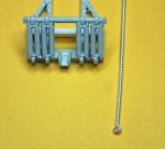
On the Airfix moldings, one of the least succesful parts of the tail were the molded "springs" holding the mechanism from the transversal beam. I guess that they might be easily replaced with copper wire...
I am going to put this on hold for 2 days as my partners Dad passed away this lunchtime.
However, just to give you some ideas:
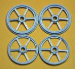
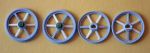
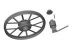
Wheel spokes - the appearance of the wheels can be enhanced by replacing the spokes with something finer - on the real thing the spokes appear quite spindly. Carefully remove $ spokes from each wheel allowing the remaining pair to support the hub and rim, cut and fit fine styrene strip spokes. Allow these to dry completely - say a couple of days, after that you can either shave down the remaining original pair of spokes, remove and replace them or even leave them as is.
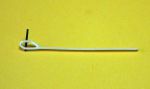
Diego has mentioned the spring assembly and was wondering about replacement. Well, I have a possible solution: In the photograph below you will see a finely wound 'handle' with a loop in the end - this is the 'handle' of an acupuncture needle (Classic Original Chinese style). The handle is silver plated copper. These might well work and the loop in the end could fix one or other end to the support. For those of you in the UK; I have 200 unused, unopened needles that are past their 'use by' date (not sure if that means you can use them on an Airfix kit!!?). The needle itself is fantastic for making aerials for tanks etc - springy and seriously strong medical grade stainless steel. Get in touch if you would like some. Diego, for you and others overseas, I suggest a visit to your local acupuncturist to see if they might sell you some. To be honest I am not going to promise to try and create the spring unit with these as I am now a Master Box convert - but we shall see.
Great suggestions, both! I'll try my hand at the wheels first, later on I'll see what I can do about the frame (which seems more labor intensive) and last, I'll tackle the springs. This trick for replacing the spokes in stages is very cunning!
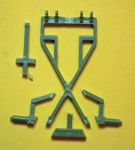
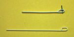
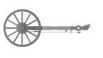
Something that you can be making whilst waiting for the next instalment is the steering tiller arm.� In the photograph is my first ever effort which I prised from an Airfix tail unit to photograph.� It gives you an idea as to the general appearance.� Dimensions are:� overall height of the loop = 2mm (almost exactly the same as the depth of the axle itself.� try and make an even loop at the rear with the front being almost vertical.� So don't copy mine as the rear, especially, is wrong and should re-join the length of the arm at about a right angle.� At this stage leave the overall length at 35mm.
� The black 'pin' represents the pivot pin for the tiller arm in the rear axle.� The photo of the real thing should better explain the angles and attachment
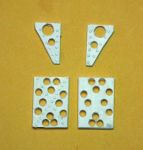
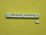
The Airfix bracing plate is about as wrong as it is possible to be and the forward triangular plates are missing totally. The rectangular bracing plates are 7mm wide and 10.5mm long (you might find it advantageous to make the length a fraction longer and trim once the holes have been drilled. (If you look at my plates you will see that the forward set are slightly more cramped and they should look the same as the rear group of 3). Al the lightening holes should be clear of the frame X member. I suggest fitting the top unit and drilling through from below, then add the bottom plate and, using the top plate as a template, drill the lower holes. Something to consider: We will be using .25mm strip to join the X frame to the axle, I suggest the rectangular brace is made from, say .4mm styrene and the front end is bevelled to give it the appearance of being thinner - we shall butt the .25 strip up to it. Alternatively stick it on top of the .25mm strips. Use the frame to give the measurements for the triangular bracing plates, you need 4 but could get away with just 2 - they need to go as far forward as the front edge of the 2 short cross beams. My samples do not reach back that far. Please note the rivet details for both the rectangular and triangular plates (again, if it isn't heresy to say it, don't bother with the rivets on the bottom plate(s) - unless you intend displaying your tank upside down!!).� The rivets on the rectangular plate are 13 and 7; on the triangular plates the rivets are equidistant along the 'straight' inner edge and the outer rivets sit in alignment.
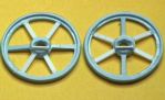
The wheels. If you wish to show a bit of steerage then you need to modify the inner wheel sections - using a round file elongate the inboard sections of the hubs horizontally (if you do this correctly the appearance of the hole should remain round when viewed from the other side). It doesn't matter how the 'slots' compare to the position of the spokes. The steering mechanism attachment point needs some work, I have cemented some fine styrene strip to the bottom of the inner wheel hubs, once fully dry, I will trim them and add the steering rod. (For real there is a piece of angle attached to the hub to which the steering arm is bolted? - see photo in earlier post). I am assuming that you don't want the wheel to rotate - so stick the hubs on the outer wheels (of interest - the Airfix hubs have more detail on them than the Master Box equivalents). Again, if you want the wheels to show steerage, you need to trim the axle stubs to about half their length; you might want to think of doing this once the stubs have been stuck back on the new axle.
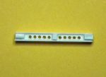
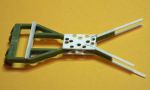
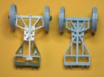
Today I have done some further work on the axle - Firstly the wide parts of the casting need to be created. Using styrene that will fit into the recess of the H-section, cut 2 pieces with an angle and fit them at either end of the axle; cut and fit a triangle into the middle of the axle. It doesn't matter if these parts sit proud of the axle as this excess can be trimmed/filed flush. See the photo for the positioning of these parts. The reverse of the H-section can either be mirrored or, as I have done, basic pieces of styrene can be added as reinforcement. Although I am not building this for any tank I plan to make, I decided to drill the, quite significant, holes in the axle. The holes are .75mm (1/32") and are 1.1 mm apart, the holes in the end of the axle only go partway through the casting.
The next stage is to add the reinforcing plates, the L angles top and bottom (note the correct orientation of the top vs the bottom). Finally the 'extensions' that connect the X beam to the axle. I have dry fitted the axle to show the position. The photos say it all really.
I've not bothered with the lower triangular bracing plates as this 'tail' will be discarded once complete.
Trimmed and stuck together. Here is a comparison with the original Airfix tail. I am working on the brake actuating arms at present, once they are done I'll set the wheels up and add the tiller etc.
Thank you Helen, I would raise issue with accurate, should we perhaps say 'more convincing'? After all it is difficult to make a silk purse from a sow's ear. My efforts to complete this tail unit will be delayed as I am off to my canal boat for a week. So if anyone is following this I do apologise. I have made the steering arms and the 'bit with the operating pullies on' - to make the pullies I used a leather punch set on the minimum hole and punched disks out of styrene sheet. (They are perhaps slightly on the large size, but then they are all but invisible except on close inspection!!
__________________
Regards TeeELL
Growing old is compulsory, growing up is optional.
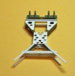
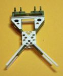
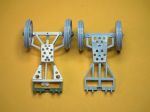
I sat down and finished the major construction of the Airfix steering tail. I have set the wheels off centre added the steering arms and connecting arms and fitted the tiller off-set to match the wheels. The connecting arms have a Y end that affix above and below the steering arms - I have fitted them above the steering arms only, so used my rivet tool to make a pimple where the pivot bolt would sit. For anu pedants amongst you: there should be a further angle iron across the bottom of the steering tail as support for the front end of the tiller, In photos it is slightly smaller than the angle iron used on the steering tail. It is held in place and at the correct spacing by a bolt at either end. I do not plan to proceed with this project as I do not intend making any Airfix tanks (I have 3 shells suitably modified to Mk1!!). If I think about it, I may spray this unit so you can see the end result, but it shall be discarded.
�
In the attached photos you can see the upper and lower views - note the pulley wheels�to operate the tiller.
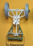
OK I offer this for those of you who whish to model the actuating system. I have interpreted this from Helen's (Mk1 Nut) various drawings - I comment you to study them before setting too on this mod. The Actuating cable exited the tank body from the forward edge of the rear horns. The cable passed around it's respective pulley and then returned to the frame of the tail unit where it was fixed. Overall this appears to have provided force advantage for the steersman ie 2:1 advantage at the pulley and about 3:1 with the tiller. So overall 6:1 to steer wheels that were trying to move a 28 ton tracked behemoth!
It really is looking a lot better than than the original kit offerings, you should be proud of what you have achieved. What is more, you have pushed me to get my drawings for the Tail Mechanism finished. I'm not quite there yet, but a lot nearer and more accurate than it was.
I've attached a few screen grabs. Ok a few weeks work yet, but close at last. The Ram and Bottle thing that sit in front of it are already done. Having said that I'm going to get some more photos from Bovi and maybe a few measurements if I can twist their arm. :)
Ah! I see, you haven't 'put the rivets in' so to speak. Although I made the comment I was in some doubt that you would have error end in such a manner.
__________________
Regards TeeELL
Growing old is compulsory, growing up is optional.
Diego,
You mention earlier, that the springs on this Airfix tail are the least satisfactory part. Well, I can tell you that they are finer than those provided by Master Box although the attachment to the cross bar is not so fine and the method of fixing leaves something to be desired. I have nearly finished the MB modified tail and I will post photos of the AIRFIX and MB units.
__________________
Regards TeeELL
Growing old is compulsory, growing up is optional.
I have completed all I plan to do with this AIRFIX unit, it has had a coat of primer but will now go into a box and be sent to a mate to enhance his collection of AIRFIX models. Please feel free to ask anything on the construction of this item otherwise I suspect this to be my final post on this thread.
PLEASE NOTE: Part no 28 (the hydraulic actuator) is shown on the AIRFIX plans of both 'Male' and 'Female' tanks UPSIDE DOWN!!! That is why the tail unit doesn't sit properly. You will see it placed correctly in the photos attached.
-- Edited by TeeELL on Friday 28th of March 2014 03:46:44 PM
The latest information I have received from Helen (Mk1 Nut) suggests that the pair of holes in each of the thickened ends of the axle should pass all the way through. It seems I have been mislead by a repair to the Bovvy steering tail. So, please drill the holes all the way through.
I commend a visit to the Mk 1 drawings in the Reference section as Helen has just submitted her latest plans of the steering tail.
__________________
Regards TeeELL
Growing old is compulsory, growing up is optional.
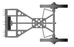
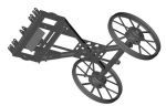
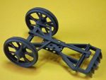
Many years later!! The advent of home use 3D printers has created an opportunity to produce parts that can enhance and/or correct some of the errors in older models. If you have read through this thread (perhaps even used the techniques) then you will appreciate the time and effort needed to correct the balance/steering tail. The other day, I decided to revisit the steering tail frame but using Fusion360 CAD software. In a fraction of the time, I had a replacement designed and printing.
The image shows the underside of the printed replacement, the only correction I need to make is the forward end of the ‘tiller arm’ where the 2 pulleys are.
-- Edited by TeeELL on Monday 22nd of September 2025 09:14:02 AM
__________________
Regards TeeELL
Growing old is compulsory, growing up is optional.
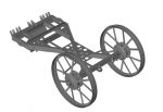
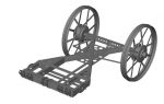
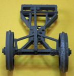
Having produced my replacement balance/steering tail frame, I realised that I had overlooked the pivot point attachments which, in turn, caused me to realise a few other issues.
From my previous image, this CAD drawing has revised steering arm lengths, slight shortening of the tiller which has positioned the pulleys a little further back. Major changes are the extended inner longitudinals and the pivot points for attaching to the hull inner sides.
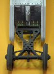
This shows the position for the pivot point in the hull sides:
__________________
Regards TeeELL
Growing old is compulsory, growing up is optional.
I’ve moved to a different image host but it has a very different way of configuring/preparing the image files for loading into various specific web sites. I’ve requested that Landships II be added - which has been -but it has yet to be ‘accepted’ by whomsoever/whatsoever does that. As soon as the upload ability is activated I will show images of the 3D printed steering/balance tail plus my replacement wheels and hydraulic jack. In addition, I produced a drill jig so that the pivot points in the inboard rhomboids for the tail frame are aligned. I have produced a print of the armoured (?) jacket that sits around the hydraulic jack but the spacing of the original Airfix ‘springs’ are sufficiently out thus preventing the jacket from fitting - but the jack and jacket can be seen on photos of Mk1s without the full tail/balance gear.
__________________
Regards TeeELL
Growing old is compulsory, growing up is optional.