Landships II

Members Login
Username 
 
Password 
    Remember Me  
Post Info TOPIC: Mark IV with interior.


Colonel

Status: Offline
Posts: 210
Date:
RE: Mark IV with interior.
Permalink   


Luca,

that looks great! How did you do the pipes?

I wonder if the radiator should be a bit higher... but it may be an illusion due to the missing mounting.

Cheers,
Thorsten

__________________


Field Marshal

Status: Offline
Posts: 421
Date:
Permalink   

Incredible work!
It will be a reference!
Regards
Gilles(lostiznaos)

__________________


Major

Status: Offline
Posts: 142
Date:
Permalink   

Hi Thorst

Thanks for having a look and for your comment. Your opinion are important  for mesmile


The pipes are simply made with metallic wire

IMG_2262a.jpg

To be honest there are more than in the real thing, due to the diameter of the wire. There is a photo in the Owners'Workshop Manual ( p.37 ) showing the pipes are about 30 and I made about 40, even though the ones close to the edges are covered, resulting in 35-36 visible pipes in my radiator.


As a reference for this building I'm using drawings like these ( I'm not sure if there is any copyright, so they are "for discussion purposes only" ) :

MarkIV scan 4.jpg

77217_mark4_tank_lg.gif


Mark_IV_Internal_1.jpg


None of them is 1/35, and you can see that there are discrepancies among them ( as usually, I apologize for my bad English, hope you can understand what I mean ).

However it's pretty easy to change the dimension of the drawings on the laptop to make them coincident with the hull of the Emhar Mark IV.


So these drawings give an overall idea of the arrangement and the ratio of magnitude of the different elements.

Furthermore, the Owners' Workshop is really useful, together with pics found in the web and, of course, here in Landshipbiggrin


Anyway, you're right, maybe be the thing will look different once the parts will be mounted, otherwise they will be slightly altered to get a better look.


Hi Gilles

Glad you like it, and hope that can be of some use..maybe should be a faster buildingaww


Hope you keep on following and helping me.


Cheers.


Luca. 


-- Edited by Luca on Sunday 3rd of May 2015 02:03:51 PM

Attachments
__________________


Private

Status: Offline
Posts: 2
Date:
Permalink   

Hello, a really great work !

Where did you found thos so detailed plans ? Especially the first one labelled General Arrangement of Machine ?


__________________


Major

Status: Offline
Posts: 142
Date:
Permalink   

Hi Nical

The plan you refer to is courtesy of MK1 Nut.

I found the second surfing and the last one here in Landships.

Cheers, 

Luca


__________________


Field Marshal

Status: Offline
Posts: 421
Date:
Permalink   

Hi!
I've bought a plan pack from Bovington museeum years ago. It included the general arrangement drawing.
Regards
Gilles

__________________


Corporal

Status: Offline
Posts: 20
Date:
Permalink   

G'day Luca,

You are doing an excellent job!

Have you considered making resin copies and selling them? I would be a purchaser.

cheers,

bj

__________________


Hero

Status: Offline
Posts: 808
Date:
Permalink   

Love the model x

I have these two photos if it helps.

Helen x


Attachments
__________________


Hero

Status: Offline
Posts: 818
Date:
Permalink   

Incredible work, please consider writing in lenght about your radiator making techniques!

__________________


Private

Status: Offline
Posts: 2
Date:
Permalink   

lostiznaos wrote:

Hi!
I've bought a plan pack from Bovington museeum years ago. It included the general arrangement drawing.
Regards
Gilles


 Thank you. They did not seems to still sell them :(

I've sent them an email for more info on this


__________________


Major

Status: Offline
Posts: 142
Date:
Permalink   

Hi Brad

You're kind, but at the moment I didn't plan to make resin copies. Above all since these parts are conceived for the Emhar kit, and I guess this kit is not so..popular today, when Takom and Tamiya released their own newer and better models.


Helen, thank you.

as usually you're a valuable source of infosaww


Hi Diego

I'll shortly post some more photos of the radiator.

In the meantime, I made that for you. Not a masterpiece, but I'm a better drawer than a writerbiggrin

20150510_142149a.jpg


Hope that can be of some use.

The details will be better described with the photos.


Regards.


Luca.


-- Edited by Luca on Sunday 10th of May 2015 03:29:31 PM

Attachments
__________________


Major

Status: Offline
Posts: 142
Date:
Permalink   

Hi again.

Second post today.,

I built the second radiator. The pipes are pretty..messy, since they will be almost completely hidden

IMG_2276a.jpg

The bolts of the radiators should be hexagonal bolts..I just made them with white varnishbiggrin


Next step to join the couple

IMG_2280aa.jpg

The red lines border the plates that complete the ensemble.

I have some doubt concerning the rim inside the green lineshmm
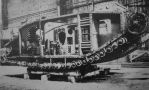
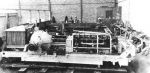
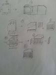
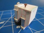
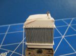
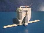
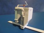
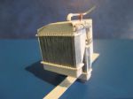
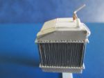
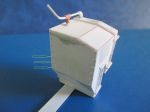
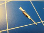
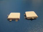
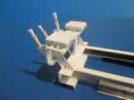
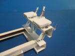
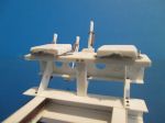
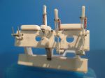
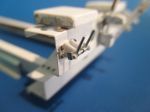
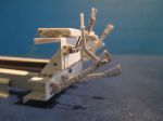
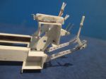
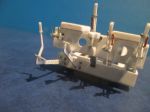
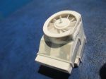
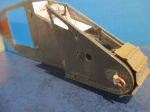
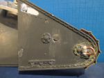
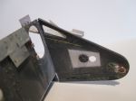
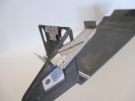
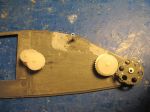
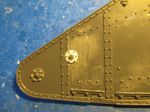
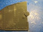
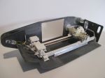
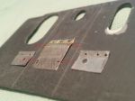
..I have the idea to remove it (and also the one on the other side, of course) since  i think that I got misled by a poor photo (and by my poor eyes). I rather guess that the back of the top of the case is a sloping plate..MMh, some more workdisbelief


And now..another revised fault inside the  red lines

IMG_2282.JPG


Here are some photos of the ensemble at the moment

IMG_2293a.jpg


IMG_2286a.jpg


IMG_2287a.jpg


That is it for now. 

Cheers.


Luca


Attachments
__________________


Corporal

Status: Offline
Posts: 20
Date:
Permalink   

G'day Luca,

Ah, but that's the point - I have an Emhar kit and, well, there are still plenty of those kits out there and being sold.

Still, it is also a matter of time and wanting to do it.

Great job and keep up the good work!

cheers,

bj

__________________


Major

Status: Offline
Posts: 142
Date:
Permalink   

Hi Brad

You're actually right, and it's a while since I want to try to work with resin.

Ok, before assembling the different parts I'll try to mold resin copies. When they should be acceptable, will be glad to give you one of themaww

In the meanwhile I'd like to be sure to make a correct jobconfuse


Here are two shots of the mods of the radiator ensemble.

IMG_2294a.jpg


IMG_2295a.jpg

The yellow arrows point to the rivets that I pressed while handing the piece. I'm going to remove them and made them better..


Not yet sure it is ok, but it looks more like the original in my reference photo.

As usually C&C very welcome.Regards.


 Luca.


Attachments
__________________


Colonel

Status: Offline
Posts: 210
Date:
Permalink   

Luca,

i like your attention to detail very much. You can be proud on it, the result is stunning!

Best regards,
Thorsten

__________________


Hero

Status: Offline
Posts: 818
Date:
Permalink   

Luca, thanks for the sketches, hope to put them to good use sooner or later!
What do you think of the Emhar kit regarding the accurcy of the general outlines? I shall do new unditching rails for it as I find the provided ones much simplifyed.
Great work!!! Keep on it!!!!!!!
D.

__________________


Corporal

Status: Offline
Posts: 20
Date:
Permalink   

Luca wrote:

Hi Brad

You're actually right, and it's a while since I want to try to work with resin.

Ok, before assembling the different parts I'll try to mold resin copies. When they should be acceptable, will be glad to give you one of themaww

In the meanwhile I'd like to be sure to make a correct jobconfuse

 ...

Luca.


Oh WOW!  I am extremely honoured!

I have been watching this with great interest.


cheers,

Brad


__________________


Major

Status: Offline
Posts: 117
Date:
Permalink   

top_skills2.png


Attachments
__________________
MRG


Major

Status: Offline
Posts: 121
Date:
Permalink   

Hello Luca,

your build is just stunning. Soo good!        I will surely look to it as reference in the future.

Best regards,


Martin


__________________


Major

Status: Offline
Posts: 142
Date:
Permalink   

Hi Thorsten

thanks for following and supporting.

Hi Diego.

Placing the Emhar kit on the drawings the general outlines and the inclination of the plates  look quite correct. The big fault of the kit is the well knowm uncorrect angle between the rear and the outer wall of the sponsons.

Concerning the unditching rails, sure the ones of the kit are not only simplified but uncorrect, too.no

As a hero, you certainly know the posts of the experts of the forum on this subjectwink

Hi Brad

hope you are a patient guybiggrin

Hi Maarten

nice to hear from yousmile

Hi Martin

your words are much appreciated..and your tips concerning the mud-chutes too..


Ok mates, in the next post some photos of the late progress

Cheers.

Luca.


__________________


Major

Status: Offline
Posts: 142
Date:
Permalink   

Hi all 

Checking the Owners' Workshop (p. 140) I noticed a photo showing that there are only three holes on the front plate of the structure where the driver's and the commander's seats are located.

First I made six holes because of..symmetry with the upper plate, but since it looks to be wrong I filled three of them.biggrin

I built the primary gear lever and its..guide. Underneath the guide there is a piece where the bottom of the lever is articulated. Unfortunately I was only able to reproduce the upper part of it because of lack of references.

So, every info concerning this area would be really useful and appreciatedaww

I built the commander's and driver's seats without the backrest not to copy the photos of the Owners' Workshop but since that will make easier having a look at the inside once the model will be completed.

Finally, I made the levers linked to the magneto and to the carburator and their bracket. I'll build the lower section of this mechanism when the engine will be in place..


IMG_2298a.jpg

The guide of the primary gear lever..


IMG_2300a.jpg

..and the primary gear lever.


IMG_2304a.jpg

The seats (without the backrest).


IMG_2310a.jpg

IMG_2308a.jpg

Two views of the levers linked to the magneto and to the carburator and their bracket.


Here are some photos of the ensemble at the moment

IMG_2311a.jpg

IMG_2313a.jpg

IMG_2320a.jpg

IMG_2323a.jpg

IMG_2315a.jpg


The parts are of course only dry fitted.


As usually C&C very very welcomesmile


A presto.


Luca.


Attachments
__________________


Major

Status: Offline
Posts: 142
Date:
Permalink   

Hi mates

First of all have a question for you experts of the forum.

I purchased this by a famous Polish producer..

IMG_2335a.jpg

..but I have some doubt, since the gun looks to be too much tapered (hope this is the right word) when compared to these photos that I found here in Landships..

Lodestar_III_43.jpg

Excellent_7.jpg

The real guns look to be actually tapered, but not as much as the "Polish" one..

I wasn't able so far to have a look at the real thing (was two times in Bruxelles, but both of them were unlucky tripsdisbelief) and, more, I'm not so used to WWI tanks, albeit to build this MK IV is my dream as a modeller..

So, I'd be glad to have your opinions, if this piece worth to be used..smile

Ok, thanks in advance and..end of part one.


Luca


Attachments
__________________


Major

Status: Offline
Posts: 142
Date:
Permalink   

Hi againbiggrin

Part two to post a little progress, the brake and clutch pedals and their swinging arms

IMG_2330a.jpg

The pedals..

IMG_2333a.jpg

...and the hand lever linked to the clutch pedal.

Here are some photos of these parts, dry fitted to the front plate of the subframe

IMG_2339a.jpg

IMG_2336.JPG

IMG_2337.JPG


As for the radiator, that's a neverending storyconfuse..

Had to narrow it, to make it fit properly to the real wall of the Emhar kit. The good thing is that now the pipes look more like the real thing..

I added the fan housing, and built the fan itself..a pure fantasy job, since I have no idea how the real thing looks and, moreover, nothing will be visible in the finished model. A waste of time, I knowno


IMG_2345.JPG

Apologies for the poor photo..

IMG_2340a.jpg

More details to be added, of course. I won't call anymore a thing donedisbelief


Thanks for watching.


Luca


Attachments
__________________


Hero

Status: Offline
Posts: 818
Date:
Permalink   

Again, wonderful work! And you having taken pictures of the fan, makes it worth the effort of building it!

__________________


Colonel

Status: Offline
Posts: 210
Date:
Permalink   

Fantastic work, Luca!


__________________


Corporal

Status: Offline
Posts: 20
Date:
Permalink   

I am constantly in awe at your build, Luca.

bj

__________________


Major

Status: Offline
Posts: 142
Date:
Permalink   

Diego, Thorsten, Brad, thanks for your kind words.

It's fine to have your feedback and supportsmile


In these days I started to work on another area of the model, i.e.the rear horns.

I have to thank Mrg since he made mention of the mud-chute cutouts, so I made them first.

IMG_2351a.jpg


I don't really know how much will be visible inside the horns in the finished model, anyway I built the return rollers and the riveted plates..better than the full vacuum

IMG_2355a.jpg


IMG_2349a.jpg


Then I modified the sprocket wheel to make it fit to the Takom workable tracks

IMG_2356a.jpg


Not a refined work, however far better than the original

IMG_2357a.jpg


Finally, I rebuilt the towing hook

IMG_2352a.jpg


Thanks again for following.aww

See you with the next post.


Luca


Attachments
__________________


Field Marshal

Status: Offline
Posts: 421
Date:
Permalink   

Very happy to see you will make corrections on the exterior too!
The Ehmar kit is not such bad but cannot pass without those improvements.
It will be a materpiece, keep posting!


__________________


Hero

Status: Offline
Posts: 818
Date:
Permalink   

Incredible work, Luca, as usual! I've always wondered myself why the kit ommited that exacy area of detailing, being a somewhat easy portion of the hull. The Airfix kit has a better mud chute than the Emhar!

__________________


Lieutenant

Status: Offline
Posts: 66
Date:
Permalink   

Superb scratch building, I am in awe of your skill.

__________________

Member of the Bridlington and Wolds Scale Model Club


Major

Status: Offline
Posts: 142
Date:
Permalink   

I agree Lostiznaos, the kit needs to be updated as for the exterior, mainly when you compare it to the today standards..

On the other hand, I always feel grateful to Emhar since we had the chance to built WWI models (not very expensive, too, I'm thinking to the resin onesdisbelief) at least until the WWI centenary did "motivate" other producers.

And sure, it's possible to get superb models using Emhar kits (you know that well, your Whippet is great!)

Diego, we were already talking about the faults of the Emhar Mk IV (the sponsons are the greater of them) and you are right in pointing the lack of mud-chute cutouts out. 

However, it's a pretty simple job to revise this kind of fault.

You're kind as usually Dave. Thank yousmile


Luca


__________________


Field Marshal

Status: Offline
Posts: 421
Date:
Permalink   

You're right!
Thanks to Ehmar to be the first to produce a MarkIV. I builded and converted so many...

__________________


Major

Status: Offline
Posts: 142
Date:
Permalink   

Hi all


Again a great delay since the last postno


I had to correct something as for the rear horn, i.e. the mud-chute cutout and the bulkhead inside..


IMG_2448.jpg

The yellow line underlines the relocated rivets. You can also notice the slight modification of the mud-chute cutout.

A big fault I was aware of at the very last moment was the uncorrect location of the round bolted plate and the round opening behind it. Now they are properly locatedbiggrin


IMG_2447.jpg

In the photo above the track guides can be seen. and the outer side of the bulkhead, too.


RC accessories are the source of the wheels that I used to reproduce the transmission system, together with two scratchbuilt wheels made with plasticard..and a scratchbuilt chain (and now you know why it took one month, to submit a new post..). Not a precise reproduction of the real thing, but similar enough, if you think that just a bit of this ensemble will be visile in the finished model.

IMG_2424.JPG


IMG_2427.JPG


IMG_2418.JPG


IMG_2428.JPG

Gearing test arrangement evileye


Ok, end of part oneaww


Regards


Luca


Attachments
__________________


Major

Status: Offline
Posts: 142
Date:
Permalink   

Hi again

Had just a snackwink..

Here is the chain assembled

IMG_2446.jpg


The position of the round bolted plate has to be modified on the outer side of the rear horns, too

IMG_2405a.jpg


IMG_2408.JPG


Some work was needed to relocate many rivets on the sides of the model. 

Moreover, some of them are hex-head ones..

IMG_2414.JPG


IMG_2415.JPG


The interior of the rear horn. 

The red arrow points out the carter to be placed over the rear section of the chain, once the assembly will be definitive.

IMG_2442.jpg


Here are some photos of a test arrangement, with the subframe and the differential case

IMG_2440.jpg


IMG_2439a.jpg

The yellow arrow of the photo above points out where the screw of the track tension adjusting system must be located. The place is empty since I wasn't able to reproduce these screws in a decent way so farno


I have to apologize. Sometimes I post photos of details that later I change, since I understand that they are uncorrect or inaccurate. It's only because I want to share a WIP work..


Ok mates, now it's time for holydaysaww

In August I'll be in Cornwall and, on the way back to London Stansted, I'll visit (it's going to be my first time) Bovington. 

Hope to spend a full day there (two, if Astrid will agreebiggrin) and maybe I'll meet some of you. That would be fine!

I'll be around the MkIV and the Whippet, taking pictures wink

However want to enjoy my holydays, and hope that you enjoy yours.

See you in September.


Luca


Attachments
__________________


Legend

Status: Offline
Posts: 1415
Date:
Permalink   

It's wonderful work Luca, far better than anything I could do. I have one question. This concerns the square plate over the (redundant) hole for the filler for the envelope radiator in the rear hull. It seems to me from your photos that you have this supported on pins at each corner and so standing away from the rear hull. If so, this incorrect. As your model has twin tubular radiators the square plate should be bolted straight onto the rear plate.

Gwyn

__________________


Major

Status: Offline
Posts: 142
Date:
Permalink   

Hi Gwyn

Thanks for having a lookaww.

As for the differences between vehicles with either envelope or tubular radiator, the Owners' Workshop says "An expert with a trained eye can distinguish between the two from the outside at the back because they had different filling and draining points, although this requires skilled and careful scrutiny.."

You are that kind of expert and I like to take advantage from your "trained eye"biggrin

20140518_093726.jpg


Anyway, because of my poor English, let me know if I correctly understood what you're referring to..

Actually in my model the plate (the one in the centre of the photo above) stands away from the rear hull, being supported on four pins (red arrows), because of that step inside the yellow lines..

I presume I was misled by this photo of Liberty (I insert it for discussion purposes only)

Liberty_7a.jpg

The arrow point out where the "famous" step seems to be..

I'm going to bolt the plate straight onto the rear hull as you say.

Are the four bolts at the corners of the plate the right way to do it?

Thanks again for your feedback Gwyn.


Regards


Luca


-- Edited by Luca on Monday 27th of July 2015 06:41:51 AM

Attachments
__________________


Colonel

Status: Offline
Posts: 206
Date:
Permalink   

Luca, this is modelling at it's best!! Keep up the good work.

Grant

__________________


Legend

Status: Offline
Posts: 1415
Date:
Permalink   

Hi Luca

I believe that all that was done with twin tubular radiator equipped Mark IVs was that the square-ish cover plate was repositioned immediately over the hole. The pins were dispensed with. So looking at your model the plate you have is much too rectangular - it doesn't reach the top of the hull but stops under the bolts at the top of the rear plate. Hope this helps. Congratulations with your model - it looks very good.

Gwyn

__________________


Major

Status: Offline
Posts: 142
Date:
Permalink   

Hi Grant
Thanks for your support and kind wordsaww


Ok Gwyn, I understand. So I have to remove the upper area of the plate to make it more..squarish, then bolt it under the upper bolt line of the rear hull plate..

Hope that you'll keep on following and checking this thread biggrin


Regards


Luca


__________________


Colonel

Status: Offline
Posts: 210
Date:
Permalink   

Luca,

your model is getting better and better! I admire your power of endurance to build the finest details in such a quality!

For the plate protecting the radiator filler hole, you can have a look at pictures of Bovington's Mark IV, which has the plate mounted at a distance as for envelope radiator tanks. But the plate's dimensions and the relative position in height should be the same, if it has not been replaced with a different one at the restorations. As far as I can tell, it agrees with the plate on Lodestar III.

Best regards,
Thorsten

__________________
«First  <  1 2 3  >  Last»  | Page of 3  sorted by
 
Quick Reply

Please log in to post quick replies.

Tweet this page Post to Digg Post to Del.icio.us


Create your own FREE Forum
Report Abuse
Powered by ActiveBoard