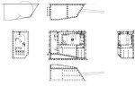
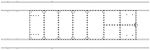
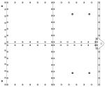
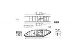
Landships II

Members Login
Username 
 
Password 
    Remember Me  
Post Info TOPIC: MK1 Tank Plans


Hero

Status: Offline
Posts: 808
Date:
MK1 Tank Plans
Permalink   


Hi everyone

Just getting back to working on plans of a MK1 Male Tank and thought it was time I should introduce myself and let you know what I am up too.

About 4 years ago now I decided I would build a 1/16 scale MK1 tank and looked around for plans ... what I found were ok but at the scale I was thinking a bit basic.

As with all plans things never go how you hope and I have not touched my drawings until just recently after a year break.

I have of course visited Bovington and also purchased some photos of their MK1 being moved to the museum ... but ... living in Portsmouth getting there is a problem as I don't drive so measurements are hard to come by. So up until know I have been using measurements I took on a visit 3 years back, and with the help of photos making a plan that has the correct detail if not always the correct dimensions.smile

I expect their is another years worth of work yet, and when finished I intend if it is good enough to donate the plans to Bovington.

I will try and get a view of the plans on here as soon as I can work at how!

So I will be around asking for help and if I can return the favour.

MK1 Nut


Attachments
__________________


Hero

Status: Offline
Posts: 808
Date:
Permalink   

Ok I think I've found a way of showing a part of my plan, the original is on TurboCad Mac Pro and I'm doing it full size ... ya gota love computer cad programs! smile

MK1 Nut


Attachments
__________________


Major

Status: Offline
Posts: 105
Date:
Permalink   

Those look great! I've a 1/24 scale MkI male in the making, and agree that redoing existing plans is necessary. However, being in the US, I'm even further away from Bovington than you, so I had to do a lot of research via photos I could find.
Your drawings are very well done and I look forward to seeing more!

Are you putting an interior in your 1/16 scale Mk I? I made a maquette in that scale, but decided on 1/24 for logistical reasons.

Some photos of my build to date are under "New Here' on the tank thread.

Best of luck to you!

Ron

-- Edited by Poniatowski on Friday 11th of September 2009 02:38:09 AM

__________________
Poniatowski


Hero

Status: Offline
Posts: 808
Date:
Permalink   

Hi Ron

Well just to prove I am completely bonkers, when I do finally start building with the help of friends, the scale may just go up to 1/6 scale !!

Oh and radio controlled ... tis mad mad mad idea! confuse

Helen xx


__________________


Major

Status: Offline
Posts: 105
Date:
Permalink   

No,

that's not mad, it's inspired. Of course you'll have to change your materials quite a bit. If I were doing it in that scale, I'd consider working in aluminum sheet and having a foundry run up the track links from patterns I've created.


Sounds like you'd have a wonderful project by the time you get done. However, the hull is easy compared to the sponsons. It's easy to see why they simplified them in the Mk IV.

Ron

__________________
Poniatowski


Hero

Status: Offline
Posts: 808
Date:
Permalink   

OK so here's my first technical question.....

When at Bovi a few years back I managed to get some dimensions of the MK2 there ... will those dimensions do for basic hull shape?

If so I already have some alterations to do as the back plate is the wrong size no
The Mark2 is 62 " wide and 54" tall. bigger than my drawing so I had better stop tweaking details and start getting the measurements right.

Helen xx


Attachments
__________________


Major

Status: Offline
Posts: 105
Date:
Permalink   

As far as I know, the exterior construction / dimensions / contours of the Mk I and Mk II is similar except along the top of the driver's 'dog house', or cupola... where the rivet spacing is diffferent at the top front (two close together on the Mk's II and III, even on the Mk I).
David Fletcher's book is a great source for photos... (Osprey publications)

yeah, draw, redraw, draw again. The story of the game. Then, following construction, a new detail or drawing gets published that puts part of the build into the trash. Unless you have an actual 100% original vehicle in front of you, one can never be sure.

Ron

__________________
Poniatowski


Hero

Status: Offline
Posts: 808
Date:
Permalink   

Hi

So I've just finished the front view to the new measurements.
Anything you think I have missed let me know.

Helen xx


Attachments
__________________


Major

Status: Offline
Posts: 105
Date:
Permalink   

Very nice!

Ron

__________________
Poniatowski


Hero

Status: Offline
Posts: 808
Date:
Permalink   

Helloooo everyone

Found out I had more measurement than I realised ... sooo here's the new rear panel with the older smaller one to show just how far out I was.

Helen xx


-- Edited by MK1 Nut on Wednesday 16th of September 2009 11:16:03 PM

Attachments
__________________


Hero

Status: Offline
Posts: 808
Date:
Permalink   

Hi
Well the top view is now to the new measurements and it's time to test the depth off knowledge available here. no

smile

I am having one of those lack of good info troubles which is bound to happen when dealing with the MK1 tanks. The thing I am stuck on is the periscope exits on the cab roof top, does anyone know if they have pistol port style covers and if so which way do they pivot?

From pictures I have of MK1s there is the hint of 3 or 4 possibly bolts surrounding the holes for the periscopes which I have shown on my drawing, but thats as accurate as I can be for now.

When I am eventually finished I hope to be able to make available here a free 1/72 scale plan, and as I said before give the full size plans to Bovi if they are interested.

I hope what I have shown here so far has been of interest and help to anyone modelling my favourite Tank.

Helen xx


Attachments
__________________


Sergeant

Status: Offline
Posts: 30
Date:
Permalink   

Hi Helen,

I looked through my collection of photos of Mk 1 tanks and couldn't find anything that shows the cab roof in any detail.  I have a couple of shots of HMLS Nutty, and one of the tank park in Palestine, that show blurry detail but nothing that would help. no

Sorry couldn't be of help.  This is great work, and I'm looking forward to the finished product. 

Dave

__________________


Major

Status: Offline
Posts: 105
Date:
Permalink   

From what I could find when I drew up my plans, the periscope apertures had no covers (of course may be wrong!). The photos in David Fletcher's book didn't seem to indicate any. I just looked again and stand by that assessment.
From what I can tell, the periscopes could be rocked (elevation or quadrant) and would probably have rotated in their mounts. My guess would be that they had a locking screw to keep them in place. As far as I could tell, the periscopes were similar to those used in the trenches that you find photos of once in a while. At least, that's what I modeled mine after.

as far as mounting bolts / rivets goes, I couldn't see any in the photos, so am waiting for 100% info before I add and paint any.

Ron

__________________
Poniatowski


Commander in Chief

Status: Offline
Posts: 671
Date:
Permalink   

I probably have the same photos you have.

But in this photo (of D7) I cannot see a 'pistol-port' type closer:

http://www.flickr.com/photos/7700258@N05/3055417679/sizes/o


This one (C6) is inconclusive:

http://www.flickr.com/photos/7700258@N05/2360804923/sizes/o


A photograph of C1 Champagne on page 128 of The Tanks at Flers seems to show a round hole with 4 bolts around it. But it is a small photo!

I will check the video footage I have.

__________________
In wine there is wisdom, in beer there is freedom, in water there is bacteria.


Legend

Status: Offline
Posts: 1076
Date:
Permalink   

I enlarged an area of the same shot of D7 that Phil posted and there doesn't seem to be any type of cover.

P.S.: I checked shots of Bovington's Mk II male/female, Mk IV male, Aberdeen's Mk IV female and a Mk III male during a training exercise. There are covers on the Mk IV's but not on the Mk II or III. It seems reasonable to assume that there weren't covers on the Mk I as well. Perhaps there were covers but the sliding plate part was internal instead of being external as on the Mk IV. Best course of action would be to examine Bovington's Mk I or ask D. Fletcher about it.

-- Edited by Mark Hansen on Monday 21st of September 2009 05:35:51 AM

Attachments
__________________


Hero

Status: Offline
Posts: 808
Date:
Permalink   

Hi everyone

Thanks for the help, it's actually finding out the little details like this that I like the most.

I will email David at Bovi and get the answer, but for now I like the idea of the internal shield unit. I have now found my copy of Trevor Pidgeon's The Tanks of Flers ... a great book recommend it ... the picture is the wreck of C1 Champagne and yes shows 4 bolts or rivets around it.

I will let you know how I get on.

Thanks all

Helen xx


-- Edited by MK1 Nut on Monday 21st of September 2009 03:13:34 PM

Attachments
__________________


Major

Status: Offline
Posts: 105
Date:
Permalink   

Thanks for the bolt detail!

Anyhoo... judging from the arrangement of the bolts and the complaints by crewmen that the tanks weren't well sealed in a lot of places, my personal take would be that they didn't shield these in any way before the exterior shields. The mounts would interfere.

My thoughts...

__________________
Poniatowski


Hero

Status: Offline
Posts: 808
Date:
Permalink   

Hi

I just finished the male sponson plan ... female sponson next.

Helen xx


Attachments
__________________


Major

Status: Offline
Posts: 105
Date:
Permalink   

Excellent Helen!

I could've used that five months ago when I was making sponsons.... I mis-interpreted some photo details, but I'm not redoing the sponsons... they were a pain in the rear!

Cheers,

Ron

__________________
Poniatowski


Hero

Status: Offline
Posts: 808
Date:
Permalink   

Thanks Ron

Yep the sponsons are a right pain, I have tweaked them so many times they look little like my first attempt. Thankfully when I ordered some photos of the Mark1 being disassembled to be moved to Bovi, and in amongst those was some of the sponsons on the ground viewed from the underside.

One thing I have learnt from all this is don't believe just one photo, and there is no such thing as standard spacing between rivets.

Hey your model is just great and I can't wait to see more pictures ... hint ... hint wink

Helen xx


__________________


Major

Status: Offline
Posts: 105
Date:
Permalink   

I posted more photos (engine etc) and think you've seen them.... so thanks for the encouragement!

Cheers,

Ron

__________________
Poniatowski


Hero

Status: Offline
Posts: 808
Date:
Permalink   

Hi Everyone

Just to prove I haven't disappeared completely I have a picture of the underside for you ... sorry about the poor quality I will work out a way of making a better copy soon.

I seem to have been jumping here there and everywhere on the plan tweaking it, I have become a rivet counter! no

smile

Helen xx


-- Edited by MK1 Nut on Saturday 14th of November 2009 12:53:06 AM

Attachments
__________________


Legend

Status: Offline
Posts: 1414
Date:
Permalink   

Fear not - a rivet counter is not a derogatory term!

Gwyn

__________________


Major

Status: Offline
Posts: 105
Date:
Permalink   

Helen,

Those look great! I've counted many a rivet for my model and I'm sure I didn't do as well as you.

Ron

__________________
Poniatowski


Lieutenant-Colonel

Status: Offline
Posts: 179
Date:
Permalink   

winkIt looks as if you are making a truly excellent contribution to the study of this vehicle, and I am sure that there are many observing who would love to see a complete set of drawings which would capture the more tantalising aspects of the Mk. 1. Please keep us informed!smile

__________________


Hero

Status: Offline
Posts: 808
Date:
Permalink   

Hi everyone

Thanks for the encouragement xxx

I have been doing a lot of juggling of rivets and I think I am now 90% happy with the side view.

I think this is as good as it will get until I get to Bovi once more with a tape measure ... problem there of course is the MK1 is out of bounds, and the MK2 is now in the main hall.
I'm happy with the detail now but I still have this nagging doubt about some of the measurements I a few years back of the MK2.

One thing I did notice and altered, was the shielding at the bottom of the sponson doors for dropping the spent shell casings out off was too small.

I think I have found a way of making a 1/72 scale plan, and I will make that my next target.

Thanks

Helen xx


Attachments
__________________


Lieutenant

Status: Offline
Posts: 65
Date:
Permalink   

Excellent!
I hope to see Mk2 side view wink


-- Edited by kapitan on Friday 27th of November 2009 08:16:06 PM

__________________


Hero

Status: Offline
Posts: 808
Date:
Permalink   

What! a MK2 !!!!!!!! confuse

Hmmm ... a few extra rivets ... new hatch ... er ... NO! ... well not yet. smile

Actually before that I must start on the Tail Wheel and Mechanism, I may be suffering from Christmas excess by the time you see that.

Anyhoo here's a quick test for a 1/72 plan. Easiest way of doing it I could think off was to put a 2cm square on the plan so you can adjust your printer to match.

Oh and change your printer settings to borderless

Let me know what you think!

Helen xx


-- Edited by MK1 Nut on Saturday 28th of November 2009 01:37:26 AM


-- Edited by MK1 Nut on Saturday 28th of November 2009 01:39:52 AM

-- Edited by MK1 Nut on Saturday 28th of November 2009 12:31:12 PM

Attachments
__________________


Major

Status: Offline
Posts: 105
Date:
Permalink   

Looks great Helen!

Are you going to make larger scale plans as well?

Ron

__________________
Poniatowski


Hero

Status: Offline
Posts: 808
Date:
Permalink   

Hi Ron

The plan is actually full size as I'm using Turbocad Mac Pro, so all I need to do is put a square of a set size on the plan. All anyone has to do is play with their print settings until the square is is the size it states, and the plan will be to scale.

I will see if I can do a test 1/32 side view.

Helen


__________________


Hero

Status: Offline
Posts: 808
Date:
Permalink   

Ok this is a side view at 1/32 scale ... biggest problem I find is the printers ability to vary the size of the image. the 2cm square being half a millimetre out makes a big difference to the tanks length ... not sure if there is an easy way round this?

Helen xx

Just made the box 20m high by the length of the 1/32 Tank ... I think this will make it a tiny bit easier ... ish!

Hxx


-- Edited by MK1 Nut on Sunday 29th of November 2009 12:37:15 AM

Attachments
__________________


Major

Status: Offline
Posts: 105
Date:
Permalink   

Ahhhhh.... nice! Added some rivets near the fuel tanks that I missed, thanks!

I'm not too familiar with CAD, only worked with squares and rules myself.... so... I guess I'm a dinosaur.

Cheers!

Ron

__________________
Poniatowski


Hero

Status: Offline
Posts: 808
Date:
Permalink   

Hi Ron

I hope this doesn't cause any problems but I've noticed a difference between the left and right hand side ... this time it's bolts not rivets! smile

Helen


Attachments
__________________


Corporal

Status: Offline
Posts: 16
Date:
Permalink   

Hi peeps.

Just joined the forum and would like to congratulate MK1 Nut on such a fantastic contribution to tank study and especially the topic of the MK 1 British tank from WW 1.

I am working on drawing up plans for the Little Willie tank but still at the initial stages of design, however I will be going to the Bovington Tank museum very soon so if you would like me to check up on photograph or draw anything regarding the MK 1 tank then please let me know and I will do the best i can to help you with your project.

Jim

__________________


Hero

Status: Offline
Posts: 808
Date:
Permalink   

Hi Jim and welcome xxx

Ummmm ... there is some measurements I would like, but don't get yourself in trouble on my account.
I still think my side sponsons are the wrong shape, and the only way to be sure is measurements. I have just done a quick print out of my side sponsons, but if you cant get the measurements its OK!

If you look at the start of my posting I have pictures of a side sponson which I believe is still on show in the WW1 Hall.

Thanks for the offer and if I can help just ask!


Helen xx


-- Edited by MK1 Nut on Thursday 3rd of December 2009 11:23:51 PM

Attachments
__________________


Corporal

Status: Offline
Posts: 16
Date:
Permalink   

Hi Helen.

Thank you for the warm welcome (and kisses too ... lol).

I am looking forward to going to Bovington on either the 14th or 15th of December and I will be making an appointment with the libraries and archives department tomorrow to confirm the date. 

I need to discuss my Little Willie tank project with the L & A dept and get the permission I need to take the measurements needed to continue my plans so it will be no problem to get further permission to take measurements for the MK 1 Male Sponson for you.  If you could please, would you post separate views of the sponson sides for me so that I can print them off separately at a larger scale; this will make it easier to note each measurement on each diagram and allow me to make further measurements that may be useful for you too.

I hope that I can be a help to you in your project and would love to see a completed scalable plan set for a MK 1 British tank.

Regards Jim

__________________


Hero

Status: Offline
Posts: 808
Date:
Permalink   

Hi Jim

Thank You for doing this, I have printed them of as individual images which should make hem easier to see. If there is any glaring mistakes then let me now ... after a few tears and a box of chocolates I'm sure I will get over it! smile

One other thing you could find out about for me if you can, I noticed some holes in the exhaust plates which I have coloured in red on my drawing. Two of the plates seem to have holes near the corners, but the plate near the main hatch I think are nearer the centre or possibly off centre.
I'm also unsure if the exhaust pipes protrude up through the plates a little.

Again thank you for this!

Helen xxxxxxxxxxxxxxxxxxxxxxxxxxxxxxxx smile


-- Edited by MK1 Nut on Friday 4th of December 2009 10:03:15 PM

Attachments
__________________


Corporal

Status: Offline
Posts: 16
Date:
Permalink   

Hi Helen.

Thanks for the print outs they are perfect for putting down the dimesions on them, I will try to get as many measurements as possible for you.

Will look at the plates and try to get their measurements as well and I will take some photos of them too as a back up for your project.

Regards Jim.


__________________


Commander in Chief

Status: Offline
Posts: 730
Date:
Permalink   

Hello to everyone!
I am new on this forum, my compliments to the fantastic work! The drawings of the Mark I are a great help, I am building a model, in zinc. I still have to make some photo's and will post them later on.
It is ca 80cm long and 22cm high. I use metal, because this "looks" more like the real thing.
I have a lot of questions!
The first one: the flaps on the cupola. There are these long metal bars, each carry a hatch cover (actually two, the main one and a smaller one). The bars are bolted, with a metal strip on both edges of the cupola. But how are these contraptions constructed on the inner end? On later Marks you see a kind of frame around the windows, and they support the long iron bar. I still did not find a photo of a Mark I where you can see clearly the construction.

Kieffer


__________________


Hero

Status: Offline
Posts: 808
Date:
Permalink   

Hi Kieffer

Welcome to the site!

Sounds like another interesting project going on, remember to start a thread and let us all know how you are getting on.

Well that was a good question and had me hunting through my pictures for an answer.....

The best I can come up with is the two brackets I have coloured in Red on the picture of the MK2 tank, support the viewports by bolting through the front plate.
As you can see it all holds in place even without the side brackets, which are in fact the shields for the lift mechanism.

I hope this helps and keep in touch

Helen xx

I've added a little sketch to show how I think the bracket holds in place.


-- Edited by MK1 Nut on Saturday 5th of December 2009 03:56:59 PM

Attachments
__________________
1 2 36  >  Last»  | Page of 6  sorted by
 
Quick Reply

Please log in to post quick replies.

Tweet this page Post to Digg Post to Del.icio.us


Create your own FREE Forum
Report Abuse
Powered by ActiveBoard