Landships II

Members Login
Username 
 
Password 
    Remember Me  
Post Info TOPIC: Building the Master Box Mk1 Tank


Legend

Status: Offline
Posts: 1062
Date:
RE: Building the Master Box Mk1 Tank
Permalink   


d_fernetti wrote:

I'll probably use some sort of brownish light grey (the wooden slats of my window blinds shall serve as reference) I still wonder from where to get a piece of nicely patterned mesh.


 Just a thought - because it has the potential for embarrassment for a male model-maker - but might a pair of fine denier ladies' tights provide a good covering for the roof frame? Might be able to give a fine mesh effect, and will certainly be see-through so that the frame is visible. 


__________________


General

Status: Offline
Posts: 346
Date:
Permalink   

Made me smile! I have investigated such a source as you suggest but I have not identified a suitable weave. So I am happy to use the same as I employed on the canopy for my Airfix Mk1 as shown in an earlier photo in this thread.

__________________

Regards TeeELL

Growing old is compulsory, growing up is optional.


Hero

Status: Offline
Posts: 818
Date:
Permalink   

Ditto from here: the stocking's weave pattern is different. In fact yesterday I was making a stab at colouring a piece of tulle fabric -as TeeELL recently suggested- using a paint marker. It worked wonderfully! Thanks TeeEll!
The pattern is correct, yet on my sample the weave is perhaps a bit too large for a 1/76 "chicken wire". On scale, a human fist can easily fit between each opening. I guess I'll have to raid another of my daughter's "Princess" costumes for a more suitable material.
As a matter of fact, here's a few shots of my "bomb roof" construction process, jigs and patterns. On the background, you can see the "rejects" which are plentiful...


Attachments
__________________


Hero

Status: Offline
Posts: 808
Date:
Permalink   

Oh dear god! Before you two start cutting up stockings and end up getting divorced, try etch mesh from White Ensign Modelsno

Helen x :)

thumblg_TW0171.jpg

I meant to say, they do actually list chicken wire, but it is 1.5mm mesh, not sure if that is to big????


-- Edited by MK1 Nut on Wednesday 29th of January 2014 04:10:06 PM

__________________


Hero

Status: Offline
Posts: 818
Date:
Permalink   

Nice, but unfortunately it's getting a bit complicated here to obtain goods from overseas (besides the devaluation of the local currency makes purchases abroad quite expensive).
I guess I'll have to keep scrounging from here and there and using old kits for a little! Here's the pattern I wish to find...
1272077770082_hz_myalibaba_web14_3887.jpg


__________________


General

Status: Offline
Posts: 346
Date:
Permalink   

The mesh I use works out at next to nothing per grenade cover and is possibly finer than the etch from WEM.  It is not as fine as that provided by MB themselves though.


Attachments
__________________

Regards TeeELL

Growing old is compulsory, growing up is optional.


Legend

Status: Offline
Posts: 1062
Date:
Permalink   

Diego, looking at your photos, may I ask if you remembered to draw a wider version of the plan view to use as your plans for sticking the frame together?

It's hard to tell from the photos, but it looks like the drawing that the two roof halves are made on is the same width as the drawing with the end view as well; if so, your roof halves will be too short, because the slope is not allowed for (I think the actual length of each half when laid flat is equal to the apparent length in plan view, divided by the cosine of the slope angle - which I'm guessing is around 30 degrees. A 30 deg slope would add 15.47% to the apparent length, so it's a difference large enough to matter). Or a pair of compasses would do the job more easily, come to think of it!

__________________


Legend

Status: Offline
Posts: 1062
Date:
Permalink   

Regarding mesh, the only picture I'm aware of having seen with the mesh visible is the one of C19 Clan Leslie in Rhomboid's 3rd post (on the first page). Exact pattern may have varied according to what was available to the crews, but certainly Clan Leslie had a honeycomb pattern, like TeeELL"s mesh.

Size-wise, I'd estimate the honeycomb mesh was a couple of inches across, which means about 0.7mm at 1/72 and 0.67mm at 1/76. Not exactly large!

__________________


Hero

Status: Offline
Posts: 818
Date:
Permalink   

Most certainly, I remembered. But I'm a lazy bastard and I just used the "projected plan view" for the jig.
The PDF where I got this from has the true lenghts of the structure members from which I cut the individual parts (you can see that drawing in the background) and I only used the plan view to help positioning the transversals in its place. Each transversal has one angled end, where a longitudinal central beam makes up for the "apex" of the roof. On the jig, I built one half with the "central" beam angled outwards and the other angled inwards. After clean up, the central beams will be joined along its lenght and in the correct angle and matching to the "projected plan view" of the jig. Clever, huh?wink

Regarding the end pieces... I noticed while idly perusing refence pictures, that contrary to the drawings I was working from,  on the front end, the inverted T assembly that's over the driver's compartment is placed higher than the rear cross piece, which forms the base of the triangle formed by the roof end tranversals. Here I attach a picture to explain it better
Front:
6631484887_7aa4ab0a3b_z.jpg

Rear:

4237830225_e24c972bb3_z.jpg


__________________


Hero

Status: Offline
Posts: 808
Date:
Permalink   

TeeELL wrote:

The mesh I use works out at next to nothing per grenade cover and is possibly finer than the etch from WEM.  It is not as fine as that provided by MB themselves though.


 Hiya, Actually that is a very good match... don't shoot me but it could do with being a tiny bit finer.  :)


__________________


General

Status: Offline
Posts: 346
Date:
Permalink   

Oh Helen,
you are sooooo right! But, unfortunately, the fabric industry does not cater for fine scale modellers. My mesh is as fine as it gets, the MB mesh is finer but is of square weave and, of course, only covers their interpretation of the grenade canopy - although, to be fair, it is the one most prevalent in photos. I shall certainly finish my 'male' tank in that canopy.
HMLS 'Oh I say!' will have the extended canopy with the side extensions over the sponsons. Once, of course, I have sorted out the camouflage pattern.  Hoping Rhomboid will come up with the goods as he is most knowledgeable.


-- Edited by TeeELL on Wednesday 29th of January 2014 07:52:54 PM

__________________

Regards TeeELL

Growing old is compulsory, growing up is optional.


Field Marshal

Status: Offline
Posts: 433
Date:
Permalink   

TeeELL wrote:


 HMLS 'Oh I say!' will have the extended canopy with the side extensions over the sponsons. Once, of course, I have sorted out the camouflage pattern.  Hoping Rhomboid will come up with the goods as he is most knowledgeable.


-- Edited by TeeELL on Wednesday 29th of January 2014 07:52:54 PM


Don't get me started!! biggrin

Fortunately, the clips from "Advance of the Tanks" show a portion of the camo pattern on both the port and starboard sides of A17. The photos of A13 bogged down at St. Pierre-Divion are the only other photo reference for A Company vehicles that I am aware of. There are subtle differences in the pattern employed by each company.

Colour is a bit of a guess. Stern mentions that the MkI's emerged from the factories in overall grey. I have yet to see any photos showing that the roofs of the cab, hull and sponsons, rear hull plate or the inner faces of the rear horns were camouflaged. There are references to the tanks of C and D Company being repainted after they reached France, and I'm guessing that would probably also be the case for A Company. Presumably the paint used would have been supplied from Royal Engineers stores. Common RE colours were light and dark Brunswick green, yellow ochre and burnt umber. I think that the scheme likely included grey, black, yellow ochre and brown, as there is a reference to the tanks of C Company being repainted with these colours.


-- Edited by Rhomboid on Thursday 30th of January 2014 06:04:41 AM


-- Edited by Rhomboid on Thursday 30th of January 2014 06:06:29 AM

__________________


General

Status: Offline
Posts: 346
Date:
Permalink   

Thanks Rhomboid,
That is good info. I shall look at those sources to get a feel for the pattern. I take note of your list of colours available. I am taking the option of grey for the roof , rear and inner rear horns. Wheels too I think, although photos indicate that the storage box was also camouflaged.

__________________

Regards TeeELL

Growing old is compulsory, growing up is optional.


General

Status: Offline
Posts: 346
Date:
Permalink   

I have been doing some work on the MB 'male' tank. It seemed to me that the gun barrels where a little too fine, the outside diameter of the MB offering being just 1mm in diameter at the muzzle. This would give a scale thickness of just 7mm for the barrel - a bit skinny I am thinking. The Airfix version is 1.3mm in diameter which would give a much meatier 17mm of barrel thickness. So I took the plunge and cemented Airfix barrels on to the MB receivers. Just waiting a while for the cement to cure.

__________________

Regards TeeELL

Growing old is compulsory, growing up is optional.


General

Status: Offline
Posts: 346
Date:
Permalink   

I've been looking again at video footage of "Oh, I Say!" and the fabric I thought was attached to the trailing edge of the Grenade canopy on the right appears more to be grass and debris caught up on bits of overhanging chicken wire.  Not so the other side which seems more substantial.

The footage of Advance of the Tanks that I would like to study in depth ( and snaffle some stills) seems to be available only off YouTube. The IWM film will not be available for DVD release until next year. So if anyone has some good quality stills of Oh,I Say! that might allow me to design a camouflage pattern, I would be most grateful.


-- Edited by TeeELL on Thursday 30th of January 2014 09:57:39 PM

__________________

Regards TeeELL

Growing old is compulsory, growing up is optional.


General

Status: Offline
Posts: 346
Date:
Permalink   

Just been putting some more bits on the 2 MB tanks. Thought I was being very careful removing the inverted V exhausts, removed 5 successfully but broke the 6th 
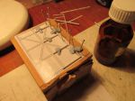
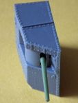
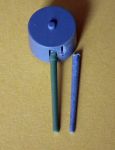
. Still it went back together OK.
Slow progress at the moment as I am having to build a 'death by PowerPoint' presentation on aircraft stability!!

__________________

Regards TeeELL

Growing old is compulsory, growing up is optional.


Hero

Status: Offline
Posts: 818
Date:
Permalink   

TeeELL! Since these pieces are angled flat rectangles, wouldn't be easier to cut them out of thin styrene (or brass sheet) and fold them?

__________________


General

Status: Offline
Posts: 346
Date:
Permalink   

Well, yes it would. But why do that when MB provide them!!

__________________

Regards TeeELL

Growing old is compulsory, growing up is optional.


General

Status: Offline
Posts: 346
Date:
Permalink   

The idea of etched exhaust deflectors was one of the options for my proposed sheet of etch. See different thread.

__________________

Regards TeeELL

Growing old is compulsory, growing up is optional.


Hero

Status: Offline
Posts: 808
Date:
Permalink   

Seeing as you are enjoying working with tiny, tiny, parts... would you like to do them the right shape? :)

Making the 1/6 scale model, I stitched together from different photos a more accurate idea of the exhaust baffles shape. If you take a close look at the Grenade roof 3D images I provided you will see them in situ.

Oh the red lines and arrows are to do with bending, so ignore those, or at least don't cut to them.


-- Edited by MK1 Nut on Friday 31st of January 2014 10:39:01 PM

Attachments
__________________


Hero

Status: Offline
Posts: 818
Date:
Permalink   

Wow! There's something new I learn every day here. I never realized the baffles had that shape! Thanks Helen!
What's the apex angle? I can't seen it in this drawing. Also, what is the height of the "triangle" in real life? Thanks in advance!

__________________


Hero

Status: Offline
Posts: 808
Date:
Permalink   

The angle on the drawing is 125% using one side as the flat and bending the other back on itself to get the 'V' shape. That's how I was shown how to do it anyways. confuse

I can't remember the height of the baffles but they come nearly level with the cab.


__________________


General

Status: Offline
Posts: 346
Date:
Permalink   

Eeeek!!! Diego, now you know why I used the kit supplied exhaust baffles.

__________________

Regards TeeELL

Growing old is compulsory, growing up is optional.


Hero

Status: Offline
Posts: 818
Date:
Permalink   

Worry ye not! Yesterday, taking advantage of the bearable temperature, I sat down and scaled the exhaust baffle drawings. They're roughly 1.5mm wide and each "leg" has about 3.75mm long. The aperture angle is a given, as it's fixed by the base width of the kit's part molding of the exhaust plaques. As for the converging sides of the baffle shape... well, that's easily cured with just a smidge of a nail file, as it's so slight in 1/76 scale that anything else is overkill!

__________________


Hero

Status: Offline
Posts: 818
Date:
Permalink   

Here's the result of today's efforts (not sure if this must go in this thread, since they're not for the MB Mk.I) but given I'm following it and the discussion a few days ago was about the bomb roof, here's a in-the-works shot of mine (I'm building two Mk.Is at the moment, one of each sex)


Attachments
__________________


General

Status: Offline
Posts: 346
Date:
Permalink   

Well reader,
I've not published much recently on constructing these MB Mk1s. Too much faffing about constructing a replacement tail steering unit and extended grenade canopy - both for my benefit and neither to do with the original kits!!
I have put together one of the 'male' sponsons for you to peruse - as you can see, unlike the Airfix offering there are all but no gaps in the gun port. I have also put a photo up of the Airfix Hotchkiss 6lb'er barrel and the surgically removed MB offering - make your own minds up as the whether I made the right decision. I believe the MB offering comes to too fine a diameter at the muzzle (as per earlier post).


Attachments
__________________

Regards TeeELL

Growing old is compulsory, growing up is optional.


General

Status: Offline
Posts: 346
Date:
Permalink   

Diego (and anyone else with the remotest interest!!),
I have attached some images of the grenade canopy I made for my Airfix Mk1 conversion. For me, the advent of the MB offerings makes all those models redundant!! I am even disillusioned by the MrX offering.
The ruler, as you will probably guess is displaying millimetres/centimetres. Note how similar the grey MB version is dimensionally to my brown effort, I added the vertical struts this morning, which is why they are white. As previously mentioned I skewed, applied de-perspective and resized a photo before taking my measurements. (Can't find that re-worked photo to demonstrate though!)


Attachments
__________________

Regards TeeELL

Growing old is compulsory, growing up is optional.


General

Status: Offline
Posts: 346
Date:
Permalink   

I have attached photos of an MB 'Male' sponson with its Airfix equivalent. It clearly demonstrates the very close tolerances of the MB offering.  Despite the tight fitting, the guns can be moved and positioned readily (even pushing my Airfix barrels!!)


Attachments
__________________

Regards TeeELL

Growing old is compulsory, growing up is optional.


Colonel

Status: Offline
Posts: 233
Date:
Permalink   

Hello,

Your grenade canopy looks nice but when I look at some pictures, the diagonal struts look more flat, maybe made of steel.
Regarding grenade canopy, I did mine for "We're all in it" and according to some pictures, it seems that there are extentions over the sponsons. Any idea is it was done like that from the beginning or the extension were added later ?

Your comment about the size of the guns is very interesting, I will check what I can do. The best possibility, but not the less expensive, should be some brass turned barrels. I don't think that a producer will do them, too small market.

Regards,


__________________

Eric

On going : Obice da 305/17 su affusto de Stefano, Mark 1 female ...

Finished : Dennis 3 tons lorry, Jeffery Poplavko, Renault EG, Renault FT


General

Status: Offline
Posts: 346
Date:
Permalink   

Eric, I agree that the diagonal bracing strips should be finer, I've learned that over the past few weeks doing this build. No idea when the side extensions were added. I am planning on building 'Oh, I Say!' Which had side and rear extensions.

__________________

Regards TeeELL

Growing old is compulsory, growing up is optional.


Hero

Status: Offline
Posts: 818
Date:
Permalink   

TeeELL! In my opinion, the scratchbuilt roof you made is far, far better than the moulded piece of the MB kit. My own example -as you saw- differs in small details from yours, but seems to be built up basically in the same way. I bet that real ones had these slight differences as well. I was tempted to make on with extended covers for the sponsons (like "A" company roofs) but that's still in the fog of future developments.
Now some silly questions:
How is the tulle fabric attached to the frame? Matt varnish? CA glue?
How much is the approximate lenght of the "legs" of the roof connecting to the tank top?

The sponson pictures are impressive... shows how the molding technology has improved in 40 years. Note how crisp are the viewing slits! I'm not too convinced, however, with the shape of the Lewis MG shields. Note how the rifle covers are positioned differently. I assume that Helen got them better than Airifx 40 years ago...


-- Edited by d_fernetti on Monday 3rd of February 2014 03:54:29 PM

__________________


General

Status: Offline
Posts: 346
Date:
Permalink   

Diego,
I used PVA adhesive (white wood glue) to attach the fabric and, to be honest, I am finding it increasing useful for modelling (it will hold vehicles and figures in a diorama and dries clear - it can also be used to make headlight lenses in small scale vehicles.

The 'legs' on my canopy are approx. 5mm in length, but it all depends on where you position them along the canopy rails. Trial and error. I broke one of the legs on the canopy (plastic rod) and had to replace it but used some .5mm carbon fibre rod, in truth not really any stronger but certainly finer. For the MB canopy I shall use some .25 carbon fibre rod I think.

Best way of getting the legs right: drill hole through beam (at right angles to beam) cut 10mm rod and pass through each of the 4 holes, adjust each rod until the grenade cover is level along and across the tank roof. When happy that all is square and correctly spaced MEK the rods and, when dry, cut the excess from the outside, smooth, paint and apply netting. Once that is done paint and fix the diagonal bracing strips (thinnest section plasticard) again using PVA as it sticks well enough to the painted plastic.

__________________

Regards TeeELL

Growing old is compulsory, growing up is optional.


Hero

Status: Offline
Posts: 818
Date:
Permalink   

Thanks! The leg positioning sure makes more sense than my own harebrained idea (not yet tried)... drilling the tank roof!
I also use white glue in some modelling tasks, like airplane rigging anchoring. Allows some working time and in case of error -which are frequent in these fields I know- it's easily removable with water.


-- Edited by d_fernetti on Monday 3rd of February 2014 04:59:00 PM

__________________


Hero

Status: Offline
Posts: 870
Date:
Permalink   

Having just returned from a stay in hospital for a large op, I made sure I had a male and female to keep me occupied 
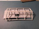
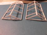
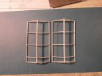
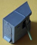
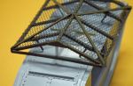
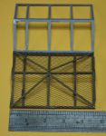
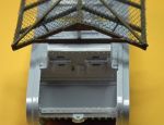
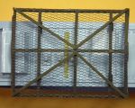
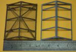
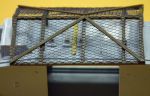
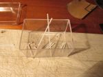
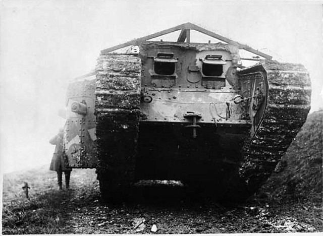
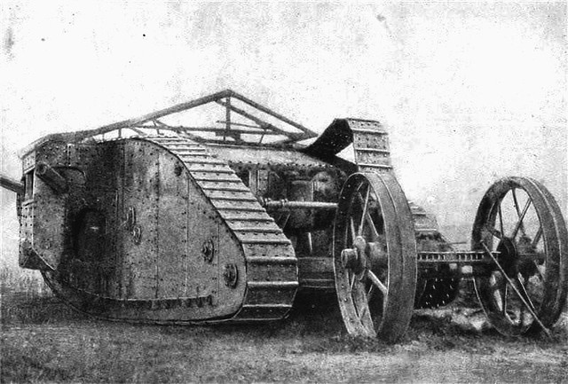
But I should have guessed nothing is ever easy. In an effort to keep things accurate do I now scratchbuild the tail unit and anti-grenade roof or just accept we have not an accurate oob build yet. lol
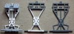
Paul

__________________

 The finest stories of the Great War are those that will never be told.


Hero

Status: Offline
Posts: 818
Date:
Permalink   

Resistance is futile, Paul.

__________________


General

Status: Offline
Posts: 346
Date:
Permalink   

Paul,
I have nearly finished my modified Mk1 tail unit. It involves constructing the X beam from channel, the rear axle from H section and attaching to the most forward bits of the MB tail unit. I will post some photos when things have cemented together firmly.

__________________

Regards TeeELL

Growing old is compulsory, growing up is optional.


General

Status: Offline
Posts: 346
Date:
Permalink   

Here are the promised photos of the tail unit. from Left to Right:

Airfix conversion     My semi-scratch build     Master Box offering (without the etch addition - see earlier posts)


Attachments
__________________

Regards TeeELL

Growing old is compulsory, growing up is optional.


Legend

Status: Offline
Posts: 1062
Date:
Permalink   

Diego, you won't like this, but I think I see an error in your roof; I think you were the one who observed that the front crossmember (the one resting on the cab roof) sits higher in the frame than the rear crossmember, but the photos suggest that your frame has little difference, if any - shouldn't the front beam be higher up?

__________________


Hero

Status: Offline
Posts: 818
Date:
Permalink   

Well, indeed the rear crossbeam is almost in the same position as the front one... and here's a result of the combined changes I made from the materials, to the drawings, each half resulted in one beam thickness thinner than it should. Overall, the differnece is not too much (I checked against the roof piece width and it gets to cover it fine) but it lacks the amount of "overhang" over the tracks that it should. Oh well, I can live with that!

__________________


Hero

Status: Offline
Posts: 808
Date:
Permalink   

TeeELL wrote:

I have been doing some work on the MB 'male' tank. It seemed to me that the gun barrels where a little too fine, the outside diameter of the MB offering being just 1mm in diameter at the muzzle. This would give a scale thickness of just 7mm for the barrel - a bit skinny I am thinking. The Airfix version is 1.3mm in diameter which would give a much meatier 17mm of barrel thickness. So I took the plunge and cemented Airfix barrels on to the MB receivers. Just waiting a while for the cement to cure.


 Hi,

I did a little bit of measuring and 1.3 is nearer the correct diameter for the muzzle at 1/72. 

In some photos it does appear to have a fair bit of tapering on the barrel, so I can see were the confusion comes from. Now don't 'shoot me' for this, but could you just chop a bit of the barrel length to make it look about right? :)

Helen x


__________________
«First  <  1 2 3 4 5 6  >  Last»  | Page of 6  sorted by
Quick Reply

Please log in to post quick replies.

Tweet this page Post to Digg Post to Del.icio.us


Create your own FREE Forum
Report Abuse
Powered by ActiveBoard