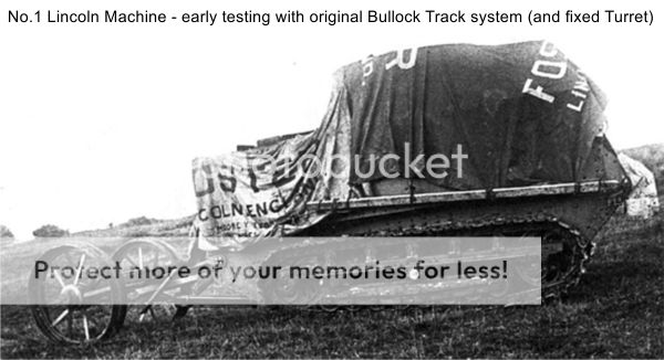
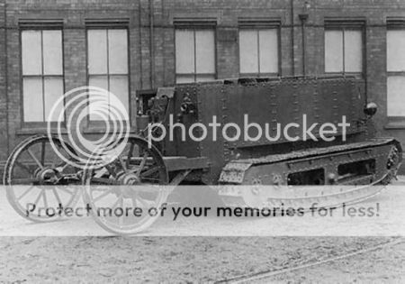
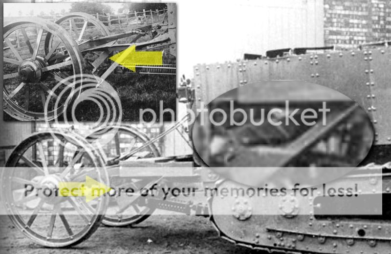
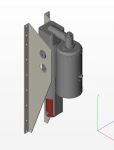
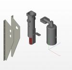
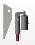
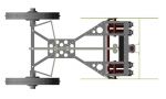
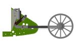
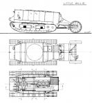
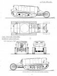
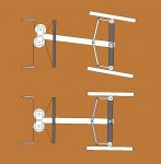
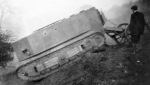
Landships II

Members Login
Username 
 
Password 
    Remember Me  
Post Info TOPIC: Steering (Tail) Unit for Little Willie and Mk.1 Tanks


Major

Status: Offline
Posts: 126
Date:
Steering (Tail) Unit for Little Willie and Mk.1 Tanks
Permalink   


Posted a query in another thread. Not sure if anyone saw it since it was a specific topic about some specific photos.

So, I think I'll repost the questions here, in case anyone can offer assistance.

First off, I'm wondering how similar Little Willie's steering Carriage assembly
is to the Mk.1 assembly.
Obviously there is a difference in the mounting, and the extended framework at the rear of the Tank
but the rest of the construction has similarities.

I ask this because I am attempting to create a (paper) model version to add to my Lincoln Machine (Little Willie) model.
I have collected a number of vintage photos (including the ones mentioned in this thread), but lets face it, things are not clear in these old photos.

AND...there are a number of obvious differences between the early Lincoln Machine and the later (Little Willie).

earlyTrittonmachine001.jpg

Are there any blueprints or clear diagrams of the steering carriages on the Mk.1 to look at?

I'd like to compare to Little Willie's steering carriages.

...
I think I have most of the steering carriage framework sorted out...
just a lot of angle iron (that I can see from the photos)

willietail.jpg

My biggest problem is the steering cable attachments and whatever is on top
and near the center of the carriage..

Obviously the cables come down to a point within the steering linkages
but its hard to figure out the bracketry, and mounting.
Do the cables connect directly to something?
I would assume they make 90 degree turns and connect to the outboard linkages?

So, is there guide wheels? or are the cables just run around a corner?


There seems to be a plate...a mounting surface for whatever connects the cables?

The hydraulic system is slightly off center, to the right side, which means the cables don't
come down into the carriage centered. This isn't a problem for steering operation (one cable
will be slightly longer), but the central hardware must be off center in the carriage too.

I think this is the clearest photo out there...its all I've got that shows this area.
Anyone got any ideas?


...

Now, heres another thing...

On the early version of the Tail Unit, there is an angle iron cross beam between the outside "skid" beams?

But on the Press photos of Little Willie, it appears to have different end plates and a large Leaf Spring spanning the assembly.

My question is, to what and how is the leaf spring attached at the center?

Does the Mk.1 tail unit have a leaf spring? and how does it attach?


steeringspring.jpg


__________________


Hero

Status: Offline
Posts: 808
Date:
Permalink   

Hi, My knowledge of Little Willy is next to nothing, I am ashamed to say, but I can help with some idea of how the Tail Assembly goes together on the MK1 Tank.

Both Tail assemblies have the same Wheels and Axle, probably straight off the spares shelf at Fosters. You can see from the photos of Little Willy how the tail developed and grew with the size of Tank.

One difference to note, is that the wheel axle and steering arms hang underneath on the MK1 Tank. It always seemed an odd thing to do, but I'm guessing that it was seen as a handy stowage space quite early on in the design... just a guess. confuse

Helen x

It's funny how you just suddenly notice something! :) The steering arms are on the top because the springs are underneath. The springs are there as the Tail Assembly attaches directly to the stern of the tank. On the MK1 the pivot point is away from the rear on the track horns, this enables larger springs to be mounted upright before the assembly.


-- Edited by MK1 Nut on Friday 10th of October 2014 10:31:33 AM

Attachments
__________________


Field Marshal

Status: Offline
Posts: 432
Date:
Permalink   

Helen,

It's got to the stage where you know more about the Mk I and its relationship with Little Willie than the original manufacturers did!  Stunning artwork.

Tony


__________________


Major

Status: Offline
Posts: 126
Date:
Permalink   

wow, great stuff...thanks Helen!

You say "pivot point"...and I think I understand that you are referring to the up/down swing point, as it attaches to the tail end of the tank? correct?

As far as turning/pivoting, I see only that the wheel hubs swivel a small amount to create a truning circle.
The carriage unit itself is fixed in a straight line with the Tank. This also appears to be the case with the Mk.1.
I bring this up, because in some old photos of various Tanks (like Little Willie) it looks like the entire carriage is angled/swiveled
and I believe this to be nothing more than a photographic and viewing angle distortion.
.....

Unfortunately there are a considerable number of differences between the Mk.1 and Little Willie's tail unit.
I'm not sure their comparison is going to help me. (not your fault)

.....
You say "springs"...I see only one spring on the Willie carriage.
It looks like a leaf spring that is mounted widthways across the carriage.
It corresponds with a cross brace that is on the earlier design,
but I don't see what it does?

Up the center (below everything) is what appears to be a dampener of some sort.
Its made up of rods (framework), end plates, a central rod or tube, and a spring type covering*.
*But it looks like flat coiled metal, rather than a spring.
This device is connected to the underside of the Tank (rear)
and the other end is connected by two long chains to the outer points of the main axle.

I assumed this was a dampener for the carriage when it extended upwards and away from the tank?
But now I am unsure.

It doesn't seem to have any connection to that leaf spring underneath.
So, what is fitted to the center of that leaf spring?
If you look at the early carriage version, and the cross bar (instead of spring)
there appears to be a bracket at the center.
But if it is connected to the same framework that it is connected to at the outer points
then it doesn't do anything...unless its just more rigidity.
And this is why I first thought it was a skid plate. a Deflector ahead of the axle and wheels.

Is that all it is? and a leaf spring adds some cushioning effect?

.....
questions questions.

earlyTrittonmachineDETAILS.jpg

..............

One more thing....that center ram/spring contraption...based on the photos of Little Willie,
and measuring the length and position of the contraption,
it appears that the later design used two shorter versions of these contraptions, connected end to end.

 Does that make sense to anyone?

earlyTrittonmachineDETAILS2.jpg


-- Edited by airdave on Friday 10th of October 2014 02:44:03 PM

__________________


Major

Status: Offline
Posts: 126
Date:
Permalink   

Well, this is turning out to be a much bigger challenge than I had anticipated!

I have built the carriage framework three times so far
and I'm still not sure I have got it right.

I was hoping to get some more info (here) but I guess this is still an obscure subject.
I appreciate the  detailed info about the Mk.1 Steering Carriage, but unfortunately it is quite different from Little Willie's.

I'm not getting all the info I need from the photos I have.
So I am having to analyze, make assumptions and mostly guess about how it all goes together.

This is the Framework I have so far:


I don't know what framework parts I might be missing from the center and underside areas.
I still don't understand how that Leaf Spring connects to something at the center?
I still don't understand where the pivot for the steering actuator is.
I still don't understand where the (hydraulic steering) cables are routed and how they connect.

I might have to settle for a basic rendition...minus a few details.
Stay tuned.


__________________


Colonel

Status: Offline
Posts: 210
Date:
Permalink   

Dave,

I have a suggestion: Look at this picture:

landships.info/landships/tank_articles/images/little_willie_9.jpg

To me it seems as the downward angled beams act as kind of a skid for the assembly, when the tail gets bent up too high. A supportive feature for this is that the underside of the beams are almost perfectly tangential to the steering wheels.

The crossbeam would then act as a limiting platform for the tail unit.

Although I am unsure if there really is a leaf spring or if it just is the beam like in the pictures before with misleading shadows, it would make sense that the collision between the tail wheel beams and the skid was softened a bit...

Just a suggestion, nothing in this post is based on knowledge!

Thorsten

__________________


Major

Status: Offline
Posts: 126
Date:
Permalink   

Thats what I said before...that it looks like a skid "plate" on either side of the frame (ahead of the wheels).

"the underside of the beams are almost perfectly tangential to the steering wheels. "
Sorry...I don't understand what this means.

or this
"The crossbeam would then act as a limiting platform for the tail unit."

The idea of a leaf spring is a little funny for me too,
but I have studied that photo up close and it sure looks a banded leaf spring.
It could definitely act as a shock suppressor though.


__________________


Colonel

Status: Offline
Posts: 210
Date:
Permalink   

With the tangential point I mean:

if you look at the side view, consider the steering wheel to be a circle. The undermost line of the angled beams would be tangents to this circle if they are elongated. This is a bit too much of a coincidence to me.

With the limiting platform I mean:

If the skid (formed from the angled beams and their connecting beam or the leaf spring) would be a bit rotatable/flexible to the rest of the tail assembly, the tail would be pressed down onto the skid by gravity when it looses ground contact (or in other words, the skid would push up the wheel assembly). The version with the beam would result in a rather harsh punch to the frame if this movement was fast, but if it was a spring, this could have been softened.

Is this description a bit clearer?


[EDIT: I just reread your posts and think that I basically agree with all of your thoughts - I should read more carefully]

Thorsten


-- Edited by thorst on Saturday 11th of October 2014 07:04:51 PM

__________________


Field Marshal

Status: Offline
Posts: 432
Date:
Permalink   

Would the Dick Harley drgs of Little Willie help?  Also, there are the drgs of Bradley and Bourguignon - but these are most probably copies of copies and i know on other tank drgs that both the latter draughtsmen have errors.

Two of Dick's drgs are set out hereunder and I would have thought that the large plank could hide a multitude of sins!!

Tony


Attachments
__________________


Hero

Status: Offline
Posts: 808
Date:
Permalink   

Hi, Just a quick diagram to show how the MK1 steering works, it is part of a discussion we had on converting some of the kits now available for the MK1.

Hope it helps.

Helen x


http://www.landships.net/t56947479/improving-the-airfix-steering-tail/

http://www.landships.net/t56621860/improving-the-mb-mk1-tanks-steering-tail/


Attachments
__________________
m83


Sergeant

Status: Offline
Posts: 38
Date:
Permalink   

here are some more photos, taken as screenshots from the following video on Landships2 (see link below)

http://www.landships.info/landships/tank_articles.html#

may be of some use - Kev

little willie 2.png


little willie 1.png


Attachments
__________________


Major

Status: Offline
Posts: 126
Date:
Permalink   

Yes Tony, I do already have Harley's drawings.
But I chose to not refer to them up to now.
I didn't like part of the rear framework- those three beams at the very back

these are not visible in photos of Willie
and are defintiely not on the early version of the steering carriage. (as you can see below)


I assumed that the drawings might have been influenced by the Mk.1 carriage
(because of lack of reference).

But now that I see the Mk.1 carriage...I can see that it is completely different again!

Helen...I have seen your diagram before. thank you.
I find it a bit confusing, actually.
The lack of the carriage framework gives the impression that the whole carriage swivels, wheras only the wheel hubs swivel.
Its also a slightly different sterring linakge layout than Willie's.

But...with all this help, I now have a better understanding of what is going on.
The more I stare at all this stuff, the more I come up with where little things go.

I'm going to pull out those Harley drawings today and add those to my design.
I think that will just about get me sorted.
However, there is still no real evidence of the steering cables routing...they may be assembled underneath that wooden florring part...
only thing I have to work with are the two earlier photos of Willie's tail.


earlyTrittonmachine003.jpg


earlyTrittonmachine004.jpg


-- Edited by airdave on Sunday 12th of October 2014 02:22:01 PM

__________________


Field Marshal

Status: Offline
Posts: 432
Date:
Permalink   

Dave,

I've been following this train of thought intently as it really is breaking new ground.

I spent many years as a structural engineer, but tried to avoid structural steelwork and stick to reinforced concrete as it was much less messy to design and draw; this conversation piece with all the different design changes proves my point!!

Looking at the second of the two photos you last posted, a certain number of things are apparent, and I will list all the points so that they are together in one place:

1)   the general carriage frame is fixed;

2)   this provides the structure on which to mount the moving components;

3)   the axle does not itself turn, but provides the stiff structure for the hubs to swivel;

4)   each hub is swivelled by a bell crank fixed to a pivot point on it;

5)   each bell crank is moved by a steel rod attached to another pivot on the central spine;

6)   both rods are the same length;

7)   these central spine pivot points on the spine are themselves moved left or right to impart an equal and opposite movement on each rod;

8)   as one rod is pushed (compressed), the other rod is pulled (tensioned) and both alter the the position of the bell cranks in opposite directions;

9)   this causes each wheel to swivel left or right to "turn" the vehicle;

10)  it is presumed that each wheel is swivelled the same amount of turn;

11)  the central spine is bolted to the axle in a way to permit rotation of the spine;

12)  compare the outer bolts on the axle - ordinary nut and bolts - to the central point that has at least one washer (presumably a second beneath the nut) to permit rotation;

13)  now look at the point where the cross-bracing is all fixed together - the two pivt points for the rods can be seen;

14)  there is no forward fixing point for the spine (which would nullify its horizontal movement);

15)  the cables attached to the front end of the spine provide the horizontal force to move the spine and the wheels;

16)  it would appear that the LHS cable goes around a pulley (and therefore returned to a fixing point that is controlled within the tank to effect the whole turning process);

17)  the RHS cable is not so evident, but must go through some similar kind of pulley system or sprung system - if it doesn't, then the wheels will only swivel once and will not be able to return to the central point again  (funnily enough, this is a problem that arose when I was researching an early locomotive to build, where the loco had only one piston but no flywheel and therefore would only work for one cylinder push.  The designer had deliberately left the second cylinder off the patent drawing - same as da Vinci and Trevithick).

It therefore shows that the turning mechanism (as opposed to the whole tail frame) is as shown on Helen's drawing.  Looking at it from an engineering point of view - if it worked on Little Willie, why change something that works when the Mk. I came along?  The question of up-scaling the whole framework to permit higher stresses for a bigger vehicle is a different matter, as would be the restriction of the vertical swing (up and down) of the wheels.

The only reason for the large plank on the frame would be to mount a mortar as per the Mk IV tadpole? (I jest).

Hope this helps.

Tony


__________________


Legend

Status: Online
Posts: 2296
Date:
Permalink   

Very interesting discussion.

If I may add an observation - the spring unit on the tail of Little Willie seems to use springs which look as if they are the recuperator

springs from a field gun. The rectangular cross section and the three short spring lengths are typical of the springs in contemporary artillery pieces.

Regards,

Charlie


__________________


Major

Status: Offline
Posts: 126
Date:
Permalink   

all good stuff guys!
I appreciate the input.

This is what I have come up with so far...and I am now satisfied with a better understanding of the basic assembly.
The photo below shows my almost finished paper model...with the wooden deck still to install,
as well as the lower tensioner (springs and chain setup).

[I've added (to the photo) the steering and lifting cables for a better understanding]

I must admit my understanding of this equipment was clouded by a lack of reference material
and complete confusion about some of the technical aspects.

First off, I never did get the fact that the hydraulics were only for the purpose of raising the carriage.
The two cables on top, nothing more than lifting cables to raise the carriage off the ground.
I always thought this was part of the steering assist.
I was constantly trying to figure out where and how the steering cables were routed.
I only just clued into the fact that the cables ran out of the body, around some guide wheels
and connected directly to the steering bar in the center.

I also never noticed the two small narrow slots in the rear corners of the vehicle (that routed the steering cables).
I kept looking at the hydraulic system and the larger holes in the back of the body for routing of the cables! lol

Obviously a big problem is the lack of photographic reference with this subject.
We have a couple of nice photos of the Steering Unit on the early Willie (pre-hydraulics).
And we have an understanding of the later Mk.1 unit.
But there appears to be some major design alterations between the three stages.

With so many changes on the fly, its no wonder there are no plans to refer to.
I can imagine all the adjustments that were probably made on the testing field.

And on top of all this, I have to simplify or stylize certain components for the purpose of designing a paper model.
A model that will be a kit, that beginner and experienced modellers can deal with.
I'm coming at this as a paper model designer. Not a WW1 Tank historian.
Luckily I have a mechanical background, so I can apply some related thinking.
But I wouldn't have figured this out without repeated analysis of the material ...and your help.
It works to bounce ideas of people who have experience with the subjects.

CharlieC...I now need to understand what "recuperator springs" are.
I know nothing about "field guns".


willietailunitpaper.jpg


__________________


Field Marshal

Status: Offline
Posts: 432
Date:
Permalink   

Charlie,

This raises another point - if the frame is fixed (by numerous bolts) in position - what would be the purpose of putting springing on it?

If one looks carefully at the framework anchor detail on the first photo (blown up as an attachment),  points become apparent:

a)  the four bolts affixing the framework to the bodywork must allow for rotation - hence the different colour of an additional plate covering the bearing through which the four bolts pass;

b)  the framework (and the bolts) would be too flimsy to support the cantilever point load of the wheels brought about by the framework moving up and down;

c)  the springs (looks like three) beneath the assembly are fixed loosely to the framework (i.e. LHS of springs showing a loose connection to the framework) and therefore would seem to be responsible for

i)   keeping the wheels down into contact with the ground (within reason); and

ii)  keeping the wheels from dropping too much when the ground falls away suddenly by the compressed springs acting as a movement limiter.

Any other thoughts on this topic?

Tony


Attachments
__________________


Major

Status: Offline
Posts: 126
Date:
Permalink   

These are my opinions:

The lower "tensioner" need only apply minimal "pull" on the axle, unless the axle(and carriage) is deflected upward.
The ram and spring work more like a pull back mechanism returning the carriage to a horizontal position.
But it must have applied sufficient pressure to keep the wheels on the uneven ground.

I see one spring/ram tensioner...but it might contain more than one flat steel coils.
Is that what you mean by three springs Tony?
We are assuming these are "coil springs"?)
Looking at the spacing between the coils, there appears to be almost no room for compression.
Maybe that explains the use of chain to connect the tensioners to the axle? No need for over compression?

However, on Willie (late 1915), there appears to be two smaller spring/ram units attached end to end
rather than one long one. (This confuses and intrigues me. What was wrong with the one long unit?
Did it buckle and bend in the middle? Are the two units connected by a solid joint or a swiveling one?)

Re: the lower leaf Spring (that I think I see in the later version)...the lower frame extensions appear to be "skids".
They are positioned almost driectly in front of the wheels and would serve to protect and lift the wheels over large obstacles.
The early carriage had a solid angle iron brace between the two "skids".
I think the change to a leaf spring, was to reduce shock and impact to the carriage framework (when the skids hit obstacles).

We know that the general concensus was "more trouble than its worth".
I think was the biggest problem for crews...lifting and trying to protect the steering carriage from damage in certain situations.
I agree the framework would not have survived any twisting forces and major impacts.

Maybe this is why the Mk.1 tail unit looks a little beefier?

Angle iron braces were added over the axle to create an anchor point for the two lifting cables

...and to add additional bracing to the frame/axle.

 willietailunitpaperrearview.jpg


-- Edited by airdave on Monday 13th of October 2014 03:36:50 PM

__________________


Field Marshal

Status: Offline
Posts: 432
Date:
Permalink   

Dave,

Fascinating stuff!

I query why you would need skids just in front of the wheels - makes no sense mechanically as the structural units are far flimsier than the wheels and a rounded surface offers less sliding resistance than a straight one.  I believe the sole reason for these "skids" was to provide a flexible fixing point between the framework and the the bottom springs (if you look closely, you will see that two of the gaps in the coils are narrower and therefore my and Charlie's contention that there are three springs).

You point about the leaf spring coming in later would bear out the stress on the original angle plate being too high when the wheels were bobbing up and down (down faster because of the tensioning effect and gravity).

All that is missing from your lovely sub-assembly is the link connection between the leaf spring and the spring tensioner (presumably left off for clarity during these discussions).

A tremendous job of work in managing to build this assembly, but also a tremendous job in adding to the knowledge base of Little Willie and the Mk. I tanks - well done!

Tony


__________________


Major

Status: Offline
Posts: 126
Date:
Permalink   

Look at this photo (I posted earlier).
This is backed up by a couple of other reference sources.

The tensioner is connected at one end to a small plate bracket, at the bottom of the Hull
and the other end is connected, by chain, to the outer ends of the main axle.

There is no connection to anything along the way.

earlyTrittonmachineDETAILS.jpg


Why do I think those side pieces are "skid plates"?

Try pulling a loaded dolly up a staircase...wheels over steps.
I used to help move heavy furniture (photocopiers mostly) and we always used sliding dollies rather than wheeled ones.


If the wheels drop into a narrow trench, or a single wheel drops into a large enough hole,
...the "skid" stops it from dropping all the way into the hole and allows it to pass over or pull out a lot easier.

If the carriage passed over a large log (for example), imagine how the log would get caught up between the front of the wheels and the underside of the carriage X-frame.

The "skid plates" would act as deflectors and the carriage would slide over the obstacle a lot easier.


I'm not the only one to come to this assumption, but the "skid" idea is only a guess, I admit. Just my opinon.


-- Edited by airdave on Monday 13th of October 2014 05:50:13 PM

__________________


Major

Status: Offline
Posts: 126
Date:
Permalink   

Well, I finally finished this "accessory".

I must admit, as with all my paper model designs, I don't include all the details.
And, I simplify many things to make them a little easier to design and build in paper.
The main axle and steering hubs are a good example of this.

I'm unsure on the type of wood used for that little deck, so I just went with a natural finish.

Cables...once again, I haven't bothered with all the technical accuracy...just fitted the basic
steering and lifting cables in place. I always leave some things (extra details) up to the builder,
since my kits are also geared towards beginners.


LittleWillie21.jpg


LittleWillie23.jpg


A few more photos here: https://flic.kr/s/aHsk4Mm2AH, if you care to take a look.

I am now putting together the final kit. It will be sold as an "accessory" kit (add-on) for the Little Willie model.

The kit will include the Steering Carriage, a printable display base sheet and the original Lincoln Machine Turret, in case you want to see what it might have looked like.


-- Edited by airdave on Monday 20th of October 2014 02:55:53 PM

__________________


Sergeant

Status: Offline
Posts: 47
Date:
Permalink   

Hi Dave,

that all looks great, I am impressed about this, but I think I see a little mistake. You put holes in the back board for the steering wires.

When I was investigating for details, I saw two slits on each side in the lower back board.

Could it be, that they are for these wires? A slit makes more sense, when the tail wheel assy is moving up and down.


Regards,

Volker


LittleWillie8.jpg 


__________________

... regards, Volker


Major

Status: Offline
Posts: 126
Date:
Permalink   

I didn't make a mistake....there are two vertical slots for the steering cables.
I assume the elongated slots allow the cables to move with the carriage.

The cables themselves are not part of the paper kit (they are wire).
The model above is my prototype...there are always small changes with the final model.

This is one of those things I discovered during the design and adjusted the final model based on the test build.

In the kit instructions I will include a template for the position of the slits
and a template for the cable(wire) placement.


-- Edited by airdave on Tuesday 21st of October 2014 02:27:27 PM

__________________


Sergeant

Status: Offline
Posts: 47
Date:
Permalink   

...ok Dave.


__________________

... regards, Volker

Page 1 of 1  sorted by
 
Quick Reply

Please log in to post quick replies.

Tweet this page Post to Digg Post to Del.icio.us


Create your own FREE Forum
Report Abuse
Powered by ActiveBoard