Hi, all: (I'm brand new to this forum and this is my first post.)
I'm working on the old 1/35 Emhar Mk IV tank and have decided to replicate a Cambrai fascine layer with this kit. I'm especially determined to do this after finding Mr. "Thorst's" brilliant auto-cad drawing explaining the device on this very forum. (Hoping "Thorst" won't mind, I've reattached it here to this thread.)
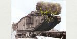
I feel like Thorsts' overview drawing (below), in particular, answers most of my questions about how the device looked and how it worked. Correct me if I'm wrong: When it was activated by tripping the hand lever in the rear of the cab, the rear restraining chains would spring forward with the fascine. (The rear chains probably stayed with the fascine to fall into the bottom of the trench along with the bundle itself.) The very front of the device strikes me as a trapeze put under tension with the crude "turnbuckle-like" tensioning device which caused the bundle to be thrust downward to be precisely placed in front of the MK IV's tracks. (So far, so good?)
My question is, how did the fascine separate from the front "trapeze"/ restraints? Were the large oval rings literally weak -break away- links? That's what I was thinking but now, I'm not so sure. Is there any workshop documentation that explains this device's operation in any detail? I have seen one apparently contemporary sketch of the release catch but that is all I've run across.
Also, the drawing is a little vague as to how the tension devise (that wound with the plank) formed a continuous loop and of what and how was it made? Braided cable? Rope? Some kind of bungee?
I would be in debt to anyone, willing to clarify details how the fascine placement worked - particularly how the fascine broke clean away from the tank as the tank moved over it and forward.
Best regards,
Frogman
-- Edited by Frogman on Thursday 16th of November 2017 09:15:28 PM
-- Edited by Frogman on Thursday 16th of November 2017 10:29:56 PM
That's something I'm also thinking about these days.. I'd added some links from other threads to merge the information, yet.
I don't have a final answer, yet - sorry!
About the ropes, we discussed here: https://landships.activeboard.com/t58344032/mark-iv-3d-cad-drawings/?page=2&sort=oldestFirst It should be ropes, though cable would be to stiff to wind with a wooden block and bungee won't hold the weight secure (and just mind what would happen if it get released!?)
It should be ropes, but where were they attached at the left/right side from the "sponson horns"?I They would't tie it at the tension track adjusting screw!
Were that ropes attached just for the transport? Other devices, as the Hayney book (p.110), shows a original drawing, were a CHAIN is attached to the front hook. So they maybe tighten them up for secure transport on the railway?
And what happend to the chain after releasing? It would be still attached on the front hook and slipped underneath the tank while driving further on. Well, maybe this wouldn't harm that much, because there might be no obstacles on the battlefield that a 28t tank couldn't handle (or the hook might break away). I can't imagine that somebody would go out side just to release it..
What do you think (or maybe know)?
(transfered from: https://landships.activeboard.com/t58344032/mark-iv-3d-cad-drawings/?page=2&sort=oldestFirst - were you'll find the release mechanism along a lot of very good CAD drawnings!)
reply
thorst wrote:
The drawing in the Hayne's manual is rather a scheme than a blueprint. All pictures I know which show the fascine in this position seem to show ropes.
After releasing, the ropes just fell off. That is why the hooks at the front point to the bottom. The lugs will just slide off.
But for a further discussion, I would suggest to start a dedicated thread with your questions, such that the topic can be found by a search in the forum in the future.
Best regards, Thorsten
-- Edited by thorst on Wednesday 15th of November 2017 05:57:36 PM ----taken rom: https://landships.activeboard.com/t63516077/fascines-and-cribs/
A thread started by me about a model of tank taking part at the Battle of Cambrai (still on work..) https://landships.activeboard.com/t64110441/grouser-tracks-and-fascine-on-mkiv-male-tank/
My enquiry for picture of fascines after use: https://landships.activeboard.com/t64109728/pictures-of-fascines-cribs-in-or-after-use/
I hope this might be useful (even to comming researchers, so they don't have to use a lot of different threads with pieces of information)
Thanks Thorst and Wolhodden (Oliver) for identifying the "Spanish Windlass" as a rope and to Olivier for describing the name and function. I would agree that I would love to see a photo of the knots for the purpose of modeling this assembly.
Does anyone have any "closeups" of the hooks with which the rope was attached at each corner of the bow of the tank? Thorst's description of them as hooks makes sense. Once the tension has been released by the handle and the fascine is jerked down and forward, the ropes would just fall away and not interfere with the operation of the tank's tracks. That seems like the "elegant solution" to the problem. I disagree that the windlass might be for travel only as the whole thing would need to remain under tension up to the moment of release. There would have had to have been enough tension to literally pull the fascine down and forward to ensure that it end up properly placed directly in front of the tank. In no way could it have been allowed to bounce "out of control" down the front of the tank lest it end up out of alignment and useless for its intended purpose.
(Thorst, I'm not understanding what you think should be done with this thread from a forum standpoint but whatever the forum managers think should be done with this topic to make it more useful to the majority of contributors and readers, I'm all for that!)
-- Edited by Frogman on Friday 17th of November 2017 07:55:32 PM
Any news about the front hooks (at the front horns) to fix the rope with the spanish windlass? I can't find any picture.
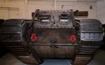
At Deborahs wreck you can see the fascine hooks on the drivers cabin (red marked, but were was it fixed forward (blue area)?
Was the rope maybe simply slung around the unditching beam rails? Or fixed on the front hook? Do anyone knew a explaining picture or drawing? Thanks a lot!
Hello
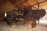
The hooks you are mentioning are in the blue circle area
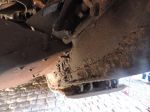
Only the one on the left side is still on Deborah. You cannot see it on this picture due to the angle.( That seems to be a round hook is the extension of the shackle shaft )
If you have others pictures of Deborah you might find it ( The hook is turned up side down , torn during the explosion)
As soon as I can I will post you a picture of this hook on a tank.
Please note that Deborah have a new home in the museum of Flesquieres.
Inauguration was held last saturday .
Best Regards
Olivier
Seems that I was looking in the wrong area, didn't mentioned it that small and upside down.
Meanwhile I'd attached the fascine on my 1/35 Tamiya kit, using the same front plates (due it worked much better on the model), what a lucky shot! (It's just awaiting a last detail, then I will show it on antother thread, if it's 99,99% finished!)
This forum and you members are a great help and inspiration!!
This now makes how it all worked seem fairly strait-forward. A pretty elegant (simple) solution that looks like it probably would have worked pretty well.
Would the hooks have been bolted on? Did people weld things with acetylene back then, at all? (Super glue? ;)
Thanks again! Interesting how the top mounts for the plank seem to have been removed from Lodestar at some time. The front hardware remains intact, however.
Does anybody have a closer view of the "Spanish windlass" rope arrangement or of the hook hardware on the front? Does Lodestar still have the handle and release hook at the cab rear?


 )
)