Landships II

Members Login
Username 
 
Password 
    Remember Me  
Post Info TOPIC: Commer Horse ambulance


Hero

Status: Offline
Posts: 818
Date:
The plot thickens!
Permalink   


Here is a comparison of the fuzzy (yet useful) drawings of the chassis of the Commer Passenger Bus (in red) and my own, incomplete, modified drawings (in Blue), made after the magazine plans, the measurements quoted and some proportions taken direct from the pictures lifted from the web and contributed by the fellow forumites.

Even when it's a very unscientific comparison, the proportions aren't very far off (the wheelbase is longer in the passenger bus chassis).

Again, I ask to the forum if someone knows the exact factory measurements of wheelbase and track of the Commer Car RC 4Ton chassis, as this would be of great help on making my own set of drawings.confuse


Attachments
__________________


Lieutenant-Colonel

Status: Offline
Posts: 150
Date:
RE: Commer House ambulance
Permalink   


Digging out one of my reference books - one that I'd forgotton all about! - I see that in 1914 the WP2 chassis was listed as wheel base 13' 8", wheel track 5' 6" and overall chassis length 23' 6"; whereas the RC had a wheel base of 12' 3", wheel track 5' 7" and overall chassis length 19' 0".

Somewhat confusingly, in 1916 and 1917 the RC is listed as wheel base 13' 3" wheel track 5' 8" and overall chassis length 20' 6".

In 1918, the wheel base is listed as 13' 3" from chassis RC4521 and 13' 9" from chassis RC4718.


__________________


Legend

Status: Offline
Posts: 1062
Date:
Permalink   

I suppose they must have produced chassis in various lengths - I think this is the case with Macks too. Dimensions may have been changed periodically according to the needs for particular types of vehicle - how large a payload was desired.

__________________


Hero

Status: Offline
Posts: 818
Date:
Permalink   

Thanks for the references!!! At last a tangible number from where to compare my drawings to scale and proportions. No worries about versions, in fact that will come useful as ....reports indicate that four CommerCar 4-ton RC chassis were supplied to... don't precisely indicate from which year the chassis were made, and I might choose the measurements closer to my own artwork.
On the original modelling magazine article, the lorry drawing  is  atypically narrow, as seen in the front and rear views.Military Modelling mag plans
commercar modelOn the French model made accordingly on  one can see more clearly that the width of the vehicle doesn't match the period pictures of CommerCar lorries 1131402?AWSAccessKeyId=1XXJBWHKN0QBQS6TGPG2&Expires=1342051200&Signature=RQPNMZhanefXDP3dX3dc4ABhidc%3D and that the thing seems to stand on "stilts", because of the high axle level under the chassis.

I think I have corrected this on my drawing, working on overall proportions from different sources, but I was still dubious on the lenght and track that I calculated from partial measurements: the chassis width is two beams wider than the bonnet and raditor, and the rear wheels track is the chassis width plus the springs, plus the chain drive case...

The body of the lorry seems to be also of the same width than the rear wheels, and is related proportionally to the width of the bonnet and radiator. As you see, there's certain double check on proportions, yet  there is no certainty at all of the sizes.

Now I have to draw the many, many things festooned all over the vehicle: flanges, hinges, hooks and rivets. Hopefully with this one may even build other types of vehicles (like, for instance, a regular cargo lorry) and in larger scales than 1:72!

Sorry to bore you all with my ramblings!


-- Edited by d_fernetti on Thursday 28th of June 2012 04:05:25 PM


-- Edited by d_fernetti on Thursday 28th of June 2012 04:09:21 PM


-- Edited by d_fernetti on Thursday 28th of June 2012 09:16:45 PM

__________________


Lieutenant-Colonel

Status: Offline
Posts: 150
Date:
Permalink   

OMG - Look what I've just found burried away in my collection, filed amongst USA vehicles. (Not for reproduction - please!)

It is, of course, a pair of CommerCars. Very similar to the RSPCA horse box but with minor differences - no chain case, a visably smaller rear vent (perhaps lower overall?) and slight differences in the cab shape and window positioning. A good view of the winding mechanism though!


-- Edited by Runflat on Thursday 28th of June 2012 08:38:00 PM

Attachments
__________________


Hero

Status: Offline
Posts: 818
Date:
Permalink   

Stunning find! At last a picture of that side! The Yanks are Commer!

__________________


Hero

Status: Offline
Posts: 818
Date:
Permalink   

Too true... Maybe the chassis braces, as the chain covers were refinements that suffered in the harsh frontline conditions... the braces hung low under the chassis and perhaps the loads in these trucks weren't so heavy as -perhaps- other types of cargo, like supplies, ammo and such, that's perhaps smaller in mass but also weighs much more than a couple of horses.
Maybe I'm wrong, but these chassis braces must have the purpose of reinforcing the chassis beams longitudinally, and also to protect the exhaust pipe and the bulky gearbox from uneven roads.
About the brake rod ending short of the brake drum.... what a mystery... seems against logic to add a system of auxiliary levers to reach the brake shoes!

Here I made a few notes over the "American" Commer photo, marking the visble brake rods in blue, and the direction of "pull" of the lever on the long segment. Now, what could possibly happen where the rods end?


-- Edited by d_fernetti on Wednesday 4th of July 2012 06:56:58 PM

Attachments
__________________
BSM


Lieutenant

Status: Offline
Posts: 51
Date:
Permalink   

I trust the attached image assists your project. A copy was passed to me courtesy of Juan Mahoney who used same in his WW1 book on the AIF. It is the one and only horse ambulance issued to the Australian Corps in France. It is Commer, Census Number 60046. The Army Mark insert is for the Vetenary Hospital. Its origin is British. Whilst this is not a good image you can make out the mark on the side of the lorry. It was returned to its RSPCA donors after the War ended.

Regards Rod.HorseVet.jpg


__________________


Hero

Status: Offline
Posts: 818
Date:
Permalink   

Thanks for the image! It shows yet another configuration and another operator of the lorries.... British, Americans and... Aussies! I wouldn't be surprised to see a picture of French veterinarians using it soon.

This phot, even if grainy, shows new features:

  • A certain census number and unit insignia (wonder if they also painted the crimson surround on the side or if they just used the white triangle).
  • It's an "early" style model, with cast spoked wheels and wooden side panels on the cab.
  •  This cab and body seem to be very alike to the American (with slight differences). No chain drive covers, these were made of aluminium, and perhaps the operators discraded them after some rough maintenance. The cab roof has a straight bottom edge front panel as well, unlike previous (British) pictures. The slatted front varies a bit, though: the Aussie ambulance has three slatted panels at front, two wide offside, and a narrow one nearside. The Yankees got 3 slatted panels as well, but with two narrow ones at each side surrounding a wide one at centre.
  • The Aussie ambulance seems a bit worn (note the broken slat at the rear) but is consistent with the looks of the entry ramp of all horse ambulances. This picture also shows -for the first time!) the extent of the folding area of the seat, and traces of the fuel tank under the front seating.
  • The folding supports under the ramp middle hinges look a  bit more complex and robust than in previous images (that IWM footage still is the best source on how they operated)

The study continues!!!!!

D.


__________________


Legend

Status: Offline
Posts: 1062
Date:
Permalink   

In addition, D, note that it lacks the chassis braces of other examples, and that the linkage for the brakes only reaches as far as the drive sprockets (the smaller, forward cogs, not the ones at the back wheels), just like on the yellow Commer bus posted earlier.

__________________


Legend

Status: Offline
Posts: 1062
Date:
Permalink   

Just to throw a cat amongst the pigeons, do you think (judging by the photos we've seen so far) that this type of Commer chassis might feature brakes that act on the transmission, rather than on the rear wheels? I have my doubts, but certainly transmission brakes have been used by some designs (Model T, perhaps?).

As for the chassis braces, somebody did say in an earlier post that they were to stiffen the chassis longitudinally; placed where they are, the braces would be under tension, resisting the bending moment created by loads. Funnily enough, steel is not necessarily the best material to use for such a job; I remember being told in a Materials Science class that wood is four or five times as strong as steel when placed under tension!

My thinking on the absence of braces is not that they suffered under frontline conditions, but that they were never fitted in the first place - I suspect it's a matter of how long the wheelbase is on a particular chassis, and the load it was designed to take.

__________________


Hero

Status: Offline
Posts: 818
Date:
Permalink   

TinCanTadpole wrote:

Just to throw a cat amongst the pigeons, do you think (judging by the photos we've seen so far) that this type of Commer chassis might feature brakes that act on the transmission, rather than on the rear wheels? I have my doubts, but certainly transmission brakes have been used by some designs (Model T, perhaps?).

That's a timely question. My almost hopeless searches on the net keep giving results, and I have found this unnamed drawing of a 6 ton lorry chassis:
A Commer chassis?
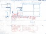
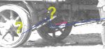
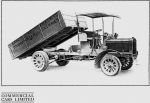
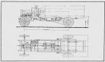
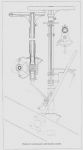
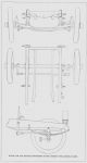
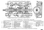
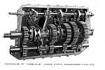
The chain gear case looks much like a Commer design, and the handwritten lettering behind the firewall seems to say "Commer Cars Lut'n" (maybe I'm seeing what I want to see?). The brake rods in the drawing, indeed, go just by the transmission driving gears. Now... why the brake drums in the rear wheels? Or maybe those look like brake drums and are just a casing for the rear chain gear? Maybe I'm getting too byzantine on this? In any case I'm learning a good deal on how an ancient lorry was made.
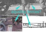
My thinking on the absence of braces is not that they suffered under frontline conditions, but that they were never fitted in the first place - I suspect it's a matter of how long the wheelbase is on a particular chassis, and the load it was designed to take.

Good point as well. Yesterday I put myself to examining the braces once again. There's a distinct device, mid lenght, that looks like a substantial adjusting screw (see attached). Any chance that these things have a proper technical name, so I can search for them with more detail? Thanks in advance!


-- Edited by d_fernetti on Sunday 8th of July 2012 08:34:34 PM


-- Edited by d_fernetti on Sunday 8th of July 2012 08:35:07 PM

Attachments
__________________


Legend

Status: Offline
Posts: 1062
Date:
Permalink   

I think this is what you want, D: the first item on the list, the knuckle joint

Not sure what the writing behind the firewall says, it's very small; there is a lot of similarity to the Commer chassis, although it doesn't have the curved-down front ends to the chassis rails.


__________________


Hero

Status: Offline
Posts: 818
Date:
Permalink   

Thanks! That's it, knuckle joint. What an able name for a biker's bar!

The full sized chassis image is here: http://etc.usf.edu/clipart/77600/77649/77649_6ton_wgnchss_lg.gif

It's for the 6 Ton chassis, so I guess that some details differ (like the curved front beams), and perhaps the gearbox and other items might have been sturdier or larger. Anyway, the general shapes and the same mechanical elements must have been the same... and it's a more clear image than the previous bus chassis diagram! Here's one image that perhaps belongs to a 6 tonner lorry:


D.


Attachments
__________________


Lieutenant-Colonel

Status: Offline
Posts: 150
Date:
Permalink   

The writing will say Commer Car Luton.

__________________


Legend

Status: Offline
Posts: 1062
Date:
Permalink   

d_fernetti wrote:

That's it, knuckle joint. What an able name for a biker's bar!


 smile Yep, you're right there! 

Thanks for the link to the full-sized pic, it's easier to read the small print. I've come across some drawings of rhomboid and Whippet tanks on that site before, but never searched through what else it has - must do so some time.


PS/PD - creo que diríamos "an apt name for a biker bar"


__________________


Hero

Status: Offline
Posts: 818
Date:
Permalink   

Some of the pictures are mislabelled, or miscatalogued... nevertheless they have a most interesting collection there!
Been doing some sketches as well, just to put the different elements "hanging" from the chassis frame in order.
The things are, from front to end:

Radiator > Engine > Flywheel >> engine transmission shaft and clutch shaft (paralell) > Gearbox > Cushion coupling (is this the exact term?) > Differential gearbox with countershaft.

Would this be correct? I think I could see most of these things exposed on the various ambulance pictures. What seems to differ from the 6 tonner is the positioning of the exhaust silencer, which in these diagrams seems to be placed transversal to the longitudinal axis (!) while on the ambulances or other lorries seem to be along the first third of the exhaust pipe close to the nearside of the chassis.
D.
PD: Note taken on "apt"!

__________________


Legend

Status: Offline
Posts: 1062
Date:
Permalink   

Your list looks right, front to back; the "cushion coupling" had me confused for a moment - the drawing isn't clear in places - but it looks to me like a large universal joint, to allow for slight misalignment between gearbox and differential.

If it's of interest, I think the drawing describes the 'engine transmission shaft' as a 'cardan shaft'.

You're right about the mislabelled pics on that sight - the Mk I and Mk V tanks are labelled the wrong way around.

PS - On second thought, "apt" is probably the word to use if you were to find a biker bar called "Knuckle Joint", but since we're speaking hypothetically it's probably better just to say "a good name...". 


__________________


Hero

Status: Offline
Posts: 818
Date:
Permalink   

I've seen the term "cushion coupling" on the description of the Commer RC chassis report, elsewhere in the net. It's a joint made up of a "cup" butting against a "disc" or "flywheel" with seemingly a soft rubber contact area. A sort of friction clutch, I suppose.
I've seen those cardan shafts on a restoration of a Dennis lorry. Interesting, wonder how much of the coupling would be visible of if it'll be obscured by some cover on the CommerCar lorry.
Speaking of getting a good view... here's a picture that would have been very valuable for this drawing project, if it wasn´t for the men standing just in front of the truck!!!!

2948179275_f7b7358785_o.jpg


__________________


Legend

Status: Offline
Posts: 1062
Date:
Permalink   

Yes, it's a good clear photo; "Left a bit lads...a bit more...keep going..."

I would guess that the cushion coupling is more for angular alignment, and not a sort of friction clutch (think if the rubber got wet, it wouldn't grip so well). Some cheaper cars in the sixties used a similar device instead of constant velocity (CV) joints - perhaps the Mini was one example, if memory serves.

__________________
Rob


Legend

Status: Offline
Posts: 1329
Date:
Permalink   

Great photo - the gorblimey caps and austerity tunics make me say 1915 or 1916. The centre standing chap, apart from the hat, is in civilian clothing, and even the hat looks to have a smooth leather brim which wasn't in use at the time, but still has an ASC badge. Chap on his right appears to have a pocket watch and the two on the lorry 'bed' have their lower pocket buttons undone!

__________________

http://www.flickr.com/photos/roblangham


Legend

Status: Offline
Posts: 2291
Date:
Permalink   


Rubber cushion couplings are common in motorcycles even today - they smooth out sudden shocks being transmitted through the drive system from the chain drive. I suspect they had the same purpose in the Commer truck.

Regards,

Charlie


__________________


Legend

Status: Offline
Posts: 1062
Date:
Permalink   

Regarding the clobber worn by the man in civvies, there's an article in the July 2012 issue of Military Machines International (by Tim Gosling, whom I believe is a fellow Landshipper) about driver training during WW1. The clothing is explained to be the uniform of the London General Omnibus Corporation; these chaps were apparently bus drivers recruited to act as instructors, and the article says they wore ASC badges on their caps.

__________________
Rob


Legend

Status: Offline
Posts: 1329
Date:
Permalink   

Thanks TCT that fits perfectly - yes, Tim is on here as 'Great War Truck'

__________________

http://www.flickr.com/photos/roblangham


Hero

Status: Offline
Posts: 818
Date:
Permalink   

Yesterday I got in my mailbox the a 1987 issue of "The Vintage Commercial Vehicle Magazine" (what an inspired title!) that I got for a reasonable price on Ebay (there was a Commer Car PS2 Chassis manual on auction as well, but at 42 quids starting price it was too rich for my blood). This magazine has a good article on Commer Car Co. history, however, to my dismay, no photos of WW1 or earlier vintage Commers. Anyway, the article stated a few interesting facts:

  • 2,303 Commer vehicles were in military service at the end of the Great War.
  • Many parts and subassemblies were made in the USA, and they had a branch in USA where they built and manufactured their own.
  • The first petrol-engined vehicle used in our Patagonian wool farms were iron rimmed 5tonner Commer cars

When I started researching these vehicles for the Horse Ambulance, I found on the internet quite a few period pictures of Commers used by the military, even when I didn't even knew the brand before this project. The style of the bodies for the Horse ambulance varied to each manufacturer, as the styles of drop side cargo lorries, and there's even a Telegraphic Mobile post out there (recognizable as a Commer Car vehicle by the characteritic chain drive covers on the rear double wheels).
Why it would be that their use isn't so known as other British brands, like AEC, FWD, Rolls-Royce or Thornycroft? Maybe they weren't "subsidized"? (the article on my mag doesn't mention it).

Anyway, I guess that a drawing of the RC chassis would become useful for a variety of projects, from supplies truck to "human" ambulances to communications mobile centres. There were also a few wheel styles to be used, from wooden spoked artillery heels, cast iron 6-spoked, and "disc" steel pressings.

I'm wondering how difficult would be to do my own PE plates for the lettering on the radiator cover and some other cast letterings all over the model. Anyway, if I consider to make the model in 1/72, there's little to show on most of them, except perhaps the COMMERCAR brand on the radiator.

PS: BTW, on the mag there's also an article on AEC during the Great War and a photo of the elusive "Berna" truck in Switzerland as mentioned in http://www.landships.freeservers.com/ww1transport_vulcan_et_al.htm , but it's a postwar development and not at all like the plan.


__________________


Legend

Status: Offline
Posts: 1062
Date:
Permalink   

Rob wrote:

Thanks TCT that fits perfectly - yes, Tim is on here as 'Great War Truck'


 Ta Rob, I was sure I'd seen his name, but couldn't remember his user name.


__________________
BSM


Lieutenant

Status: Offline
Posts: 51
Date:
Permalink   

You were looking for some info re the Commer RC. You may find the attached useful. First 3 in this post. Rod


Attachments
__________________
BSM


Lieutenant

Status: Offline
Posts: 51
Date:
Permalink   

And the next 2 files....Rod


Attachments
__________________


Hero

Status: Offline
Posts: 825
Date:
Permalink   

Any idea to what scale are the plans???

I am finding this thread facinating. As I am bringing out cavalry horses etc.This could be an ideal kit.


-- Edited by baldwin on Sunday 29th of July 2012 04:14:25 PM

__________________
Barry John


Hero

Status: Offline
Posts: 818
Date:
Permalink   

Lovely, lovely! Thanks a lot! This sure simplifies a lot my research. I've had some help too from the gentleman running the Commer heritage website. As previously seen here on the thread, there's a few conflicting measurements. As I've taken a few days off, I hope to dedicate more time to draft the variations and compare the proportions to the actual pictures, maybe there's a clue on what type(s) of chassis was(were) used for horse ambulances.
Balwin: I have made a few sketches of the ambulance body, with some variations from "early", "late" and a couple of cab styles. When I can confirm more or less the overall dimensions and proportions I would post the drawings here.

__________________


Hero

Status: Offline
Posts: 818
Date:
Permalink   

Well, as this last drawing has the measurements noted, you can bring them to your preferred scale with the aid of Photoshop and a decent printer! Note that this one had the wooden spoked wheels, and not the later (?) metallic spoked or disc variants. The chain drive covers are not drawn here, and I detect some variation regarding the fixture holding the drive axle to the chassis sides. I guess it's not too different from the wartime ambulance chassis, and the differences are mostly related to shape detail, and not function.


-- Edited by d_fernetti on Monday 30th of July 2012 02:43:25 PM

__________________
BSM


Lieutenant

Status: Offline
Posts: 51
Date:
Permalink   

No mention of "scale" for the drawings unfortunately. The information comes from a 1910 Commer, dealer's catalogue.

 Regards... Rod


__________________


Legend

Status: Offline
Posts: 1062
Date:
Permalink   

Very interesting posts, BSM - in particular the description of the mechanicals; this should help a lot in sorting out the confusion over brake linkages!

__________________
BSM


Lieutenant

Status: Offline
Posts: 51
Date:
Permalink   

Glad to be of assistance. From the same catalogue I can provide the similar details on the 3ton YC, the 5 ton CC and the 5.5ton KC if that will advance the cause! There was also a variant on the 5ton labelled the SC and one on the 5.5ton labelled the OC! The 7ton was the PC according to the document.  Rod


__________________
Rob


Legend

Status: Offline
Posts: 1329
Date:
Permalink   

Got a couple of images of a 1908 Commer used by the North Eastern Railway if those are any use?

__________________

http://www.flickr.com/photos/roblangham


Hero

Status: Offline
Posts: 818
Date:
Permalink   

Yes, everything can be used! Any views of the steering mechanism or the gearbox, visible under the chassis?

__________________
Rob


Legend

Status: Offline
Posts: 1329
Date:
Permalink   

Not that I can tell, nice view of the chain to the rear wheels on one view, interesting photos though - private message me your e-mail and i'll send them through in minutes

__________________

http://www.flickr.com/photos/roblangham

BSM


Lieutenant

Status: Offline
Posts: 51
Date:
Permalink   

Attached are images of the front end and steering gear for a 1914 Subsidy Commer.

Rod


Attachments
__________________


Hero

Status: Offline
Posts: 818
Date:
Permalink   

WoW! Thanks, Rod!

__________________
BSM


Lieutenant

Status: Offline
Posts: 51
Date:
Permalink   

Good to hear the material is of some assistance. Gearbox views attached. Rod


Attachments
__________________
«First  <  1 2 3 4  >  Last»  | Page of 4  sorted by
 
Quick Reply

Please log in to post quick replies.

Tweet this page Post to Digg Post to Del.icio.us


Create your own FREE Forum
Report Abuse
Powered by ActiveBoard