There are references to a "stroboscope" in the cupola of FCM tanks. The FCM 1A (later incarnations), FCM 2C and FCM Char de Bataille prototype were all fitted
with this device. I think I know how a stroboscope works - two slotted cylinders which rotate in opposite directions - gives the illusion of all round vision with some
brightness diminution. Anyone know how the device fitted to tanks worked?
Regards,
Charlie�
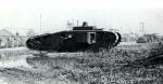
Just found an image of a Mark VIII tank with a stroboscopic cupola - no details of when and where though.
-- Edited by CharlieC on Monday 16th of December 2013 02:54:26 AM
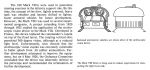
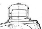
Here's what I have, from Hunnicutt's Firepower (referring to tests on the Mk VIII) and an image of the FCM 2C cupola downloaded years ago, origin unknown. Hunnicutt is pretty self-explanatory.
One thing to note is that the various online comments I've found all say that the cupola consisted of two contra-rotating concentric cylinders furnished with narrow vertical slits. While this may have been the case for the French Char 2C (though I have no evidence one way or the other), the diagram in Hunnicutt shows that this was certainly not the case for the experimental Mk VIII. An internal stationary cylinder with large vision ports apparently filled with thick glass is surrounded by an external rotating cylinder with narrow vertical slits. Only one cylinder rotates. Frankly, this seems far more likely to have been the case for the French device too, as having both cylinders rotating would have been absurdly complex (and hazardous for the observer, unless there was a third internal - stationary - cylinder patterned after the American one).
-- Edited by Roger Todd on Monday 16th of December 2013 03:32:50 AM
Perhaps the Americans got it wrong. I borrowed a copy of GBM #98 with the FCM 1A article by Guy Francois - the stroboscopic cupola gets a mention:
"Ce dispositif ing�nieux, etudi� par le capitaine de r�serve Oehmichen, adjoint technique � l'AS, consiste en deux plaques circulaires perc�es pivotant � grande vitesse, donnant au chef de char l'illusion d'une observation au travers d'un mat�riau transparent tout en offrant une bonne protection contre es balles de mitrailleuses. Tr�s performant, le stroboscope �quipera les chars 2 C achev�s apr�s la guerre."
"This ingenious device , studied by Reserve Captain Oehmichen, �technical assistant at l'AS (Artillerie Speciale) consists of two slotted cylindrical plates which rotate at high speed , giving the tank commander an illusion of observation through a transparent material while providing good protection against machine gun bullets . Very efficient, stroboscope equipped the Char 2C completed after the war."
The text clearly says two slotted cylinders and that it gave good protection against machine gun bullets.
Hah, I've got that issue and had forgotten the mention of the stroboscopic cupola!For whatever reason, the Americans must have changed the design (perhaps to reduce its complexity).
Found the image of the Mark VIII with stroboscopic cupola in Hunnicutt's book - I had only seen a cropped version before. Here's a challenge - what's the vehicle in the right background?
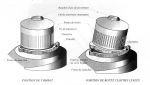
The factory photos and drawings of the Char 2C show the outer metal cylinder with view slits mounted on top of an internal cupola frame with thick armored glass.
So it's basically like the American experimental cupola and all the talk of double-slitted contra-rotating drums is wrong? Well, the double-drum arrangement always sounded unnecessarily complex to me, thanks for the info!
Not necessarily - Guy Fran�ois was writing about the FCM 1A and he may well have been describing the cupola fitted to that tank. He did not say that the same design was fitted to the
FCM 2C - just that stroboscopic cupolas were fitted to the 2C. It seems to me that the statements of Guy Fran�ois and Steve Zaloga are not incompatible but the text of the article should
be modified to reflect this.
Nice to know that the forum is being looked at by real experts.
Yes, you're right, I was getting mixed up - the FCM 1A came first and may well have had the double-drum arrangement as described and then, later, it was presumably simplified for the Char 2C and the Americans modelled their version on that.
I've altered the Landships II article to reflect Steve's comment. Would be nice to get an image or drawing of the internals of the FCM 2C cupola.
Edit: Steve beat me to it....
Steve - may I use the drawing and image on Landships II please?
Regards,
Charlie
Edit: I can see that working well - not. The electric drive motor is above the internal cupola. Unless the FCM 2C was very advanced and had slip rings on the turret floor the
power cable is going to cause problems getting tangled as the turret rotates.�
-- Edited by CharlieC on Saturday 28th of December 2013 12:48:15 AM
-- Edited by CharlieC on Saturday 28th of December 2013 01:32:51 AM
I've contacted you off-board about using the pics.
Here's another thought about the photo of the Char 2C cupola. The spacing on the slits on the outside and inside of the cylinder appear to be different. Maybe the outer cupola assembly actually consists of two layers, a fixed cylinder�and the other a rotating cylinder. The separate�inner frame has armored glass to protect against any spalling.
Looking at where the outer cupola is driven there's a ring with two studs presumably to attach to the motor �but there seems to be a similar ring for the outer part of the cupola.
I wonder if that's another drive ring? Perhaps both the inner and outer parts of the cupola were driven, maybe in opposite directions?
I took a quick look at the booklet on the Char 2C by the Saumur museum and noticed that there is a write-up on the operation of the Stroboscope. My technical French is getting rusty, but here's a quick translation. I don't think it settles the issue of the construction of the device, but maybe it contains useful details:
The Stroboscope
The combat experience of the first tanks, and especially the FT 17, highlighted the danger posed by vision slits in the hull or turret armor to the face and especially the eyes of the crew members not only from direct hits but mostly from fragments detached from the inner face by nearby hits. The first precaution against this danger was to give the crew a protected face mask formed of loose chain mail that allowed observation while still attached to the helmet. The Char 2C incorporated initial protection afforded by the design itself . The cylindrical cupola is perforated with large openings. It is topped by a circular cap provided itself with narrow vertical slits and which rotates on an axis more than about 300 revs / minute with an electric motor at the top of the turret . The principle of retinal retention is such that the crew sees the landscape in a continuous manner as through a slit or an episcope, while being protected by the turret and fairing. Only an unlucky blow, always possible, can reach the crew. The stainless steel cylinder, 30 mm thick, was perforated by 45 vertical slits 2 mm wide (over 2.5 mm they would permit the passage of steel armor piercing rounds) that could rotate around its axis. A second cupola fitted in the interior had 7 large rectangular windows of triplex glasses. This cupola was fixed relative to the first. When the outer cupola rotates at a sufficient rate, 250 to 300 revolutions/minute, the interval of time between the conjunction of two consecutive slots to the observer is less than a 1/10th of a second, so that the view of the external object appears to the eyes of the observer to be continuous (in fact the human eye retains that impression for a duration of 1/10th of a second). So that the observer has depth perception, it must offer binocular vision, that is to say, his eyes must each receive a view of the external objects . Therefore the vertical slots are arranged in a particular way in 9 groups of 5 slots. The structure under the two cupolas has three horizontal slots for a fixed observation. A screw controlled by a handle located in the turret allows during the approach march before reaching the enemy, to raise the assembly for ventilation of the turret to improve and to facilitate direct observation .
I bet it wasn't stainless steel - perhaps a nickel-chrome high tensile steel alloy. Machining the 2mm slots in a 30mm thick 18-8 stainless cylinder would be a challenge even today.
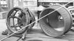
It looks like there was only a single outer slotted cylinder on the FCM 2C.
This is a nice picture of the external and internal stroboscopic turret . I've never seen this . Thanks .
For interested people , i've been published few months ago in a french review with a text ( and totally unknown pictures ) about this tank . I do not want to make any advertising , but inform you can get the internal plans of the tank on the web ( they were totally lost since WW2 ) :
http://atf40.fr/AADAM/plan2C.html
It could be interesting for modelers and historians , so don't hesitate to share the link with friends .