Landships II

Members Login
Username 
 
Password 
    Remember Me  
Post Info TOPIC: Mark V female with portable tank crane (How was it attached?)


Brigadier

Status: Offline
Posts: 299
Date:
Mark V female with portable tank crane (How was it attached?)
Permalink   


Hello Landship-members,

A question about the Mark V female tank with portable tank crane.

in David Fletchers book on the Mark V there is a drawing of this tank with some text. here is a copy of the text from the internet:

 Book David Fletcher.png

"the crane was bolted to the idler shafts on the inner face of the horns". Can anyone explain how this was done or how it looked like?

I want to replicate it and i am wondering about how it was exactly attached?

a picture would be great smile

Best regards,

Willem


Attachments
__________________


Legend

Status: Offline
Posts: 1415
Date:
Permalink   

See photo.


Attachments
__________________


Brigadier

Status: Offline
Posts: 299
Date:
Permalink   

Hello Gwyn,
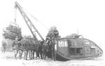
that is a great photo. It is the tank where the drawing was made from for the book from Mr. Fletcher.
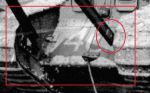
The question remains that I do not understand how they attached the crane to the idler shafts on the inside of the horns..?
Bolted on what parts? Or was it attached on an other way?
Thanks and best regards,
Willem

__________________


Legend

Status: Offline
Posts: 1415
Date:
Permalink   

See the New Vanguard on the Mark IV. Page 36.

Gwyn

__________________


Brigadier

Status: Offline
Posts: 299
Date:
Permalink   

Thanks Gwyn,
I have ordered the book. It was on my wishlist for a while and now there is a good reason to buy it......
Thanks,
best regards,
Willem

__________________
SMK


Major

Status: Offline
Posts: 118
Date:
Permalink   

Hello

I am also very interested in how the crane was attached to the tank

A few days ago I found this (for me unknown) picture in article about the chineese workforce during WW I

The_British_Army_on_the_Western_Front,_1914-1918_Q9865.jpg

Sadly still no clear picture of the attachment......

greetz

Ronald


-- Edited by SMK on Sunday 4th of December 2016 06:28:23 PM

__________________


Brigadier

Status: Offline
Posts: 299
Date:
Permalink   

He Ronald!
Great picture. As you stated, it is still not certain how it was attached.
But one thing is certain:

there is going to be a Dutch group-build of the Mark IV's and V's with portable tank cranes!

Best regards,
Willem


-- Edited by Willem Visser on Sunday 4th of December 2016 06:41:46 PM

__________________


Colonel

Status: Offline
Posts: 210
Date:
Permalink   

The "Mechanical Maintenance of the Mark IV. Tank" (General Staff, April 1918) has some drawings on the portable tank crane. It says: "Base of jib bolted on to end of road chain adjusting wheel shaft". The drawings indicate that the beams are bolted directly to the idler wheel's shaft, using the same bolt that is also used to fix the wheel in its position. This is in agreement to the picture Gwyn suggested (New Vanguard, p. 36).

The single cable or tie described in the drawings which holds the beams in their position is fixed to a hook "bolted through [the central] revolver port hole" of the driver's cab.


__________________


Brigadier

Status: Offline
Posts: 299
Date:
Permalink   

Hello Thorst,
another welcome answer!
That explains a lot. I think I understand about the way it was fixed but to be sure I ordered the book.
I was not aware of this book: "Mechanical Maintenance of the Mark IV. Tank" and found out it was still available.
Enough to read in the next weeks, and I think I know someone who wants to read them too ......

Thanks and best regards,
Willem


__________________


Commander in Chief

Status: Offline
Posts: 624
Date:
Permalink   

Assuming that the idler mount is symmetrical.
<a rel=3.bp.blogspot.com/-nT18Ci8DYdA/U7GyRML8cGI/AAAAAAAAAxQ/8qdZZzzsQ_s/s1600/IMG_1026-3.jpg">
Hollow hexagonal shaft, slides over the nut & held in place by the spring inherent in the design of the jib?

__________________


Brigadier

Status: Offline
Posts: 299
Date:
Permalink   

Hello Adam,
I do not fully understanding what you write. English is not my first language ....
Do you mean that the beams are wedged between the two sides and the bolts are not screwed to the beams?
Sorry, i appreciate your reply and would like to understand it.
Best regards
Willem

__________________
SMK


Major

Status: Offline
Posts: 118
Date:
Permalink   

hello pzkpfw-e

I also don't understand fully.

Is it like you put  a socket over the nut of the axel of the idle wheel  over which the crane jibs pivots

And like Willem states  the whole crane is wedged between the fwd track assemblies.....

is that correct?

Wouldnt there be to much force on the nut / socket connection When the crane was in use?

maybe they used longer axel pins which

Another question which arises....

But what if they had to adjust the tracktension  then the idlerwheel axels are not aligned anymore .......

found another picture


Greetz Ronald


Attachments
__________________


Lieutenant

Status: Offline
Posts: 66
Date:
Permalink   

The last pic was very interesting, I have enlarged and chopped it, note inside the circle, there is an adapter piece that attaches to the crane jib.


John


Attachments
__________________


Colonel

Status: Offline
Posts: 210
Date:
Permalink   

This is exactly the configuration described by the drawings in the mechanical maintenance manual.

__________________


Brigadier

Status: Offline
Posts: 299
Date:
Permalink   

Hello Thorst,
Then i will wait for the book. It was send to me today from England.
Those drawings will give me the exact answer.
Thanks,
Best regards,
Willem

__________________


Brigadier

Status: Offline
Posts: 299
Date:
Permalink   

Today I received the mechanical maintenance manual of the Mark IV.
Great little book and it is very clear to me now how the crane was attached to the vehicle.
This is definitely one to build in 1:35
Thanks for all your replies and the advise to buy this book.
Best regards,
Willem

__________________
Page 1 of 1  sorted by
 
Quick Reply

Please log in to post quick replies.

Tweet this page Post to Digg Post to Del.icio.us


Create your own FREE Forum
Report Abuse
Powered by ActiveBoard