Landships II

Members Login
Username 
 
Password 
    Remember Me  
Post Info TOPIC: Williams-Janney hydraulic transmission


Legend

Status: Offline
Posts: 2294
Date:
Williams-Janney hydraulic transmission
Permalink   


Was ratting through the IWM online image collection and came across two images which were captioned as a Mark IV tank

fitted with the Williams-Janney transmission and an uncaptioned third image of the rear of a Mark IV with a curious construction

added to the rear of the hull. Is this the external part of the Williams-Janney transmission?- it seems to have a header tank and radiator.

The 3 images are Q14562, Q14563, Q14564.

Charlie

The vehicle under the tarp in the background looks like the amphibious Mark IX. 


-- Edited by CharlieC on Sunday 18th of June 2017 11:54:44 PM

Attachments
__________________


Lieutenant-Colonel

Status: Offline
Posts: 174
Date:
Permalink   

This is Mk.II as we can see by cabs's rivets location.

__________________

Regards

Denis


Lieutenant-Colonel

Status: Offline
Posts: 171
Date:
Permalink   

Have you also noted in the background a tank crane under a tarpaulin in the photo of the rear of the Mk II tank


__________________

Craig Moore


Tank Hunter. Looking for the survivors.

www.tanks-encyclopedia.com

www.tank-hunter.com


Legend

Status: Offline
Posts: 2294
Date:
Permalink   


Yes - I suspect the location was Dollis Hill in North London although it doesn't state the location in the IWM image captions.

The Welsh Harp (now Brent Reservoir) where the amphibious Mark IX was tested is pretty close to Dollis Hill.

Charlie


-- Edited by CharlieC on Monday 19th of June 2017 10:46:40 AM

__________________


Captain

Status: Offline
Posts: 76
Date:
Permalink   

The apparatus in the third photo looks like a Ford Model T radiator, I assume for cooling the transmission (if it's the same tank).

jh


__________________
jch


Legend

Status: Offline
Posts: 2294
Date:
Permalink   


The external radiator may have been a lash up since the transmission was found to generate excessive

amounts of heat.

Bit of research - strictly Williams and Janney developed and patented the variable pressure axial piston hydraulic pump.

The complete transmissions with hydraulic drive motors were produced by the Waterbury company.

Waterbury made turret actuator systems for the USN and Royal Navy before and during WW1.

The IWM has images of the rear of the Mark VII trial vehicle, also with the Williams-Janney transmission, but these haven't

been released to the Internet yet. It would be interesting to compare the arrangement of the Mark VII with the Mark II test vehicle.


Charlie


__________________


Lieutenant-Colonel

Status: Offline
Posts: 171
Date:
Permalink   

Charlie if you can find me the IWM reference number I will add it to the list of documents/photos I want to see next time I go to the IWM archives, for you.


__________________

Craig Moore


Tank Hunter. Looking for the survivors.

www.tanks-encyclopedia.com

www.tank-hunter.com


Legend

Status: Offline
Posts: 1415
Date:
Permalink   

Charlie

Where do you get the name Waterbury from? I can't find a company of this name. Do you have any more information about them?

Thanks

Gwyn

__________________


Legend

Status: Offline
Posts: 2294
Date:
Permalink   


It is/was called Waterbury Tool Company based in Waterbury, CT.

Google found me a book on hydraulic engineering "Hydraulic Fluid Power - A Historical Timeline" by Steve Skinner available on lulu.com. 

I've attached screenshots of the relevant pages. The Royal Navy used hydraulic turret drives designed by Armstrongs but these used water

as the fluid - the American drives used oil as the fluid and seem to have been fairly compact. 

Stern called the drive the "Williams-Janney system" in his "Logbook of a Pioneer".

Charlie


-- Edited by CharlieC on Tuesday 20th of June 2017 03:08:18 AM

Attachments
__________________


Legend

Status: Offline
Posts: 2294
Date:
Permalink   

MooreTanks wrote:

Charlie if you can find me the IWM reference number I will add it to the list of documents/photos I want to see next time I go to the IWM archives, for you.


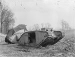
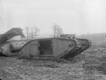
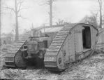
Thank you - the IWM search says there are 4 Mark VII images of interest

HU 64120

HU 64124

HU 64123

HU 64121

I think the trials were held in Scotland so the images may be of a tank in heavy rain or fog - the manufacturer Brown Brothers was based in Edinburgh.

It seems to me that I may have enough information for an article on the Mark VII tank for Landships II.

Regards,

Charlie


__________________


Lieutenant-Colonel

Status: Offline
Posts: 171
Date:
Permalink   

Charlie I have added them to the list of archive documents I want to look at. I will be going back there in the Autumn.


__________________

Craig Moore


Tank Hunter. Looking for the survivors.

www.tanks-encyclopedia.com

www.tank-hunter.com


Legend

Status: Offline
Posts: 1415
Date:
Permalink   

Thank you Charlie. This adds to my knowledge.

Gwyn


__________________


Legend

Status: Offline
Posts: 2294
Date:
Permalink   


For anyone who would like to get their head around how the Williams-Janney transmission worked...

The principles are here: https://www.youtube.com/watch?v=D6FHU54qyRE

The Williams-Janney hydraulic pump had two cylinder blocks - one with a fixed swash plate

and one with a variable plate. The attached IWM image shows the pump disassembled. In this image the 

variable pump is on the left with the actuating cylinder to move the swashplate. The fixed part on the right

is missing the cylinder block but shows the pistons. On many applications such as turrets the fixed swashplate

assembly acted as the motor for the transmission. If this is so in the Mark VII tank there were probably two

of these units - one for each track.

I can see why the hydraulic transmission attracted a fair amount of interest. A gearless

infinitely variable transmission which gave steering control by simply varying the flows to the motors certainly

is an attractive proposition.

Charlie


-- Edited by CharlieC on Wednesday 21st of June 2017 07:01:22 AM


-- Edited by CharlieC on Wednesday 21st of June 2017 09:14:09 AM

Attachments
__________________


Legend

Status: Offline
Posts: 1415
Date:
Permalink   

Charlie

Just checked my files and I have a photo of the rear of the Mark VII, though I do not have permission to publish it. The tank does not have external radiators like the EMD (the tank in post #1).

Gwyn

__________________


Legend

Status: Offline
Posts: 2294
Date:
Permalink   

Thanks Gwyn,

I have seen a comment that the Mark VII may have had a radiator in the roof to handle the heat build up in the hydraulic fluid.

It's important with hydraulic transmissions to limit the temperature rise of the fluid during operation.

Stern says there were two Williams-Janney units coupled to the rear of the engine with a 4:1 gearbox in the Mark VII.

Regards,

Charlie


-- Edited by CharlieC on Saturday 24th of June 2017 02:21:12 AM

__________________


Legend

Status: Offline
Posts: 1415
Date:
Permalink   

It definitely had vents in the roof.

Gwyn

__________________


Legend

Status: Offline
Posts: 1415
Date:
Permalink   

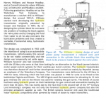
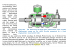
This is another IWM photo of the Mark VII but it appears sideways on their site and unless you twig that you can't make sense of it, but this shows the standard Ricardo engine, the vents in the roof, the Autovac and (I think) the two Williams-Janney units.

Gwyn


Attachments
__________________


Legend

Status: Offline
Posts: 1415
Date:
Permalink   

Oh bu88er! That's just come out sideways! Rotate the image through 90 degrees anti-clockwise.

Gwyn

__________________


Brigadier

Status: Offline
Posts: 299
Date:
Permalink   

Must it look like this?

Mk VII 150hp Ricardo engine w. Williams Janney hydraulic transmission (IWM Q14589).jpg


Attachments
__________________


Legend

Status: Offline
Posts: 2294
Date:
Permalink   


It does but the image only shows the left side of the W-J units.

What is notable are the steering rods which change the swashplate angle in the drives. They seem to have been

extremely well engineered presumably to try eliminate any backlash in the controls.

The hose which runs across the left hand unit may have been either the drain for hydraulic fluid leakage from the primary high

pressure circuit or may have been for make up fluid. Internally these drives leaked fluid from the primary circuit so there was a system

to collect excess fluid from the casing and pump it back into the primary circuit.

It's a pity the image didn't include all of the drive units. According to Stern there were bevel drives to gearboxes in front of the sprockets

for the chain drive.

I've annotated the IWM image for the people who would like to get up to speed on what this thread is about.

Regards,

Charlie


Attachments
__________________
Page 1 of 1  sorted by
 
Quick Reply

Please log in to post quick replies.

Tweet this page Post to Digg Post to Del.icio.us


Create your own FREE Forum
Report Abuse
Powered by ActiveBoard