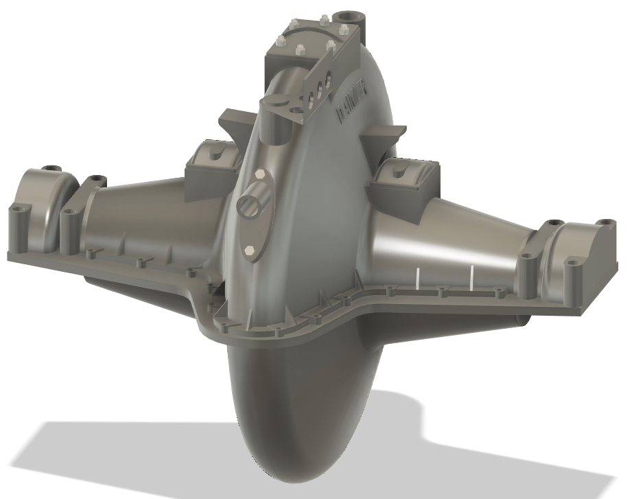
Landships II

Members Login
Username 
 
Password 
    Remember Me  
Post Info TOPIC: Mark IV Tank Engine, Differential Subframe 3D Model


Corporal

Status: Offline
Posts: 14
Date:
Mark IV Tank Engine, Differential Subframe 3D Model
Permalink   


Hello Everyone, Not new to the site but had to reset username and password due to changing emails.

Thanks to retirement and Covid it has given me a chance to do some 3D Cad modelling of Mark I, Mark IV and Mark V tanks. I have focused on getting the Mark IV tank more to completion. I like what others have shared on their 3D projects. Attached are some pics of what I have done for the engine subframe assembly. Some things are layed out for space claim and checking functionality. As more info is acquired I hope to tidy up a lot of things. There are lots of questions due to limited drawings and pictures of some areas. 

Areas needing information are:

1. Shifter mechanism by the driver controls. Some pics have helped but not sure of the bottom linkage

2. Radiator mounting feet

3. Engine and transmission mounting feet.

4. Differential, engine clutch configuration'

Please review and comment on missing areas and what other features missing and corrections needed. Your professional comments are welcome.

I read what MehdiT is doing and quite impressed. 


MARK IV SUBFRAME 1.gifMARK IV SUBFRAME 2.gifMARK IV SUBFRAME 3.gif


Attachments
__________________
PDA


Legend

Status: Offline
Posts: 1486
Date:
Permalink   

Looks good, Godzilla.

When I look at stuff like this I think of printing it out at 1/72 scale and dropping it into an Emhar or MasterBox kit.


__________________


Corporal

Status: Offline
Posts: 22
Date:
Permalink   

Hi,
Looks great.
Pat

__________________


Sergeant

Status: Offline
Posts: 39
Date:
Permalink   

Wow!
Much further along than I am.
Bloody well done!

__________________


Sergeant

Status: Offline
Posts: 39
Date:
Permalink   

this is where I'm at..

Finaldrive2-230920.png


__________________


Corporal

Status: Offline
Posts: 14
Date:
Permalink   

Bozothenutter,

Nice work. Liking the detail. I haven't got too far in detailing, just trying to get space claim and understanding levers and pedal operations. One thing I would like to point out is the bottom side of the diff needs an input pinion shaft and shaft coupling from gearbox to operate diff. There is also some type of brake mechanism on the bottom of the diff that may brake the pinion shaft into the diff.  I have been referring to GA drawing of Mark IV I got from Bovington and pics found on line. Attached is what I believe the bottom should look plus pic showing the engine, gearbox and differential assembly, Can't remember MARK IV SUBFRAME 4.gifwhere I found pic. If not allowed administrators can remove.

Godzilla

MARK IV SUBFRAME 5.gifpost-1494-0-92679000-1465643566.jpg


Attachments
__________________


Sergeant

Status: Offline
Posts: 39
Date:
Permalink   

Mine is still FAR from finished, to many pots on the boil....
Really interested in what you got from the tank museum.
Apparently they have 'package' of research available, but due to covid, I can't get one....

__________________


Legend

Status: Offline
Posts: 2292
Date:
Permalink   


Curiosity - is the differential driven by a worm gear which engages on the outer part of the large crown wheel?

Regards,

Charlie


__________________


Corporal

Status: Offline
Posts: 14
Date:
Permalink   

Bozothenutter, I ordered drawings from Bovington a few years ago. I purchased GA drawings for the Mark I, IV and V tanks plus the drawings for the shell assembly. Also use the Haynes Workshop manual and books from Osprey Publishing for reference. I have tried lately to get info from Bovington but no replies. I was fortunate to travel to Aberdeen Proving Grounds a few years ago before they moved the Mark IV to Fort Lee I believe. 


__________________


Corporal

Status: Offline
Posts: 14
Date:
Permalink   

Charlie, The inside bits and pieces are a mystery to me right now. I have searched on the internet and books and have found little info. I am assuming the diff would be be a pinion gear and crown gear. Not sure a worm gear arrangement would be able to handle the torques required. A research challenge. The big challenge is to think in early 1900 engineering.

Regards

Godzilla


__________________


Corporal

Status: Offline
Posts: 14
Date:
Permalink   

Charlie, on second thought it would probably be a type of worm to crown gear setup as you have suggested. The geometry would not be a setup for a pinion gear. As stated need to dig a little deeper.

Regards

Godzilla


__________________


Legend

Status: Offline
Posts: 2292
Date:
Permalink   


The image of the engine with transmission tipped me off that Daimler made the differential.

A quick search of the patent literature turned up a Daimler patent from 1914 for a differential driven by a worm gear

with drive splines in the centre of the wheel.

Reference is British patent GB191422816(A) - 1915-08-19 (Google patent search will get you the abstract - the full patent is at espacenet.com)

Regards,

Charlie


-- Edited by CharlieC on Thursday 28th of January 2021 09:35:08 AM

__________________


Legend

Status: Offline
Posts: 1414
Date:
Permalink   

There is a worm gear in the bottom of the differential casing. I know this because the top of the casing from Deborah is missing and I once had the opportunity to enter the tank. The tank is now alarmed so this is no longer possible without special permission.

Gwyn

__________________


Legend

Status: Offline
Posts: 2292
Date:
Permalink   


Thanks Gwyn.

Apparently Daimler used worm gear final drives from about 1909 until after WW2 - perhaps it gave a smoother power transfer

compared to helical gears.

Charlie


__________________


Corporal

Status: Offline
Posts: 14
Date:
Permalink   

Hello Charlie

Thanks for the lead on the patent. I have downloaded it and will be doing some research on worm gear differentials. 


__________________


Corporal

Status: Offline
Posts: 14
Date:
Permalink   

Hello Gwynn

Thanks for the worm gear confirmation in the differential. Both you and Charlie have been helpful.

Regards

Godzilla


__________________


Sergeant

Status: Offline
Posts: 39
Date:
Permalink   

Like this

Side-section-worm-gear.jpg


__________________


Corporal

Status: Offline
Posts: 14
Date:
Permalink   

Bozothenutter

Yes this looks like it. thanks for posting.  Is there another pic showing the differentail portion? What is the source for the picture? Looks like a parts manual.

Regards

Godzilla


__________________


Sergeant

Status: Offline
Posts: 39
Date:
Permalink   

Check your pm's

These are from the engine maintenance manual.

I have asked if I'm allowed to post them, but no reply as of yet...


Apologies for being a tease....🤷🏾‍♂️


__________________


Corporal

Status: Offline
Posts: 5
Date:
Permalink   

Interesting to see, waw!

We made an MKiv tank in Belguim but with a hydraulic engine now.

https://tankpoelcapelle.be/en/Motor_Engine


__________________


Sergeant

Status: Offline
Posts: 32
Date:
Permalink   

This is fantastic! Even though it's for a different tank, this kind of discussion makes me think I should make a thread about an article on the Ricardo tank engine I found a long time ago (p. 407).


__________________


Legend

Status: Offline
Posts: 2292
Date:
Permalink   


I can see in the 3D model where the coolant pipes run for the hot loop of the coolant system but can't pick up where the piping for the cold loop is.

Anyone enlighten me?

Charlie


__________________


Corporal

Status: Offline
Posts: 14
Date:
Permalink   

Hello Charlie,

Did some research on the for the cool loop and found there is a water pump located on the left side of the engine. Looks like it feeds cool water just below exhaust outlets. I did a quick 3D layout of what I believe how the tubes route from the bottom tanks back to engine. The image is in a simplified format for now. When the colder weather comes I will probably provide as much detail as I can find. Attached is a picture I found showing left hand side of engine and the routing of water pipes. Also included 3D screen shots of my thinking of the routing. Hopefully this answers some questions. As always info is up for discussion. 

Regards

Godzilla


6472211107_f69a0cdc2c_b.jpgengine cooling 5.gifengine cooling 4.gif


Attachments
__________________


Legend

Status: Offline
Posts: 2292
Date:
Permalink   


Thank you - that answers my question comprehensively.

I guess like most engines of that time the cooling system operated close to atmospheric pressure. I don't know when pressurised systems

became the norm.

Regards,

Charlie


__________________


Sergeant

Status: Offline
Posts: 39
Date:
Permalink   

one of the things that attracted me to 3D modelling, being able to see/deduce what went where.


__________________


Corporal

Status: Offline
Posts: 8
Date:
Permalink   

Hey guys,

I have a quick question relating to the engine subframe that maybe someone can answer, how was it attached to the hull of the tank? By looking over the original drawings of the Mk. VI (in the Haynes Manual... still trying to contact Bovington to get my own copies) it would appear that most of the hull strength is in the track frames... did the subframe tie into those or was it simply bolted to the (relatively) thin floor plates?

__________________


Corporal

Status: Offline
Posts: 14
Date:
Permalink   

Hello ChaseR83

MARK IV SUBFRAME ASSY.gifFrom what I can determine the engine/differentail/radiator subframe is bolted at the rear to the floor plate(red bracket) and to the sides at front of the subframe (blue brackets). From the blueprints the bolt holes are in the rear floor plate but don't see mountimg holes in side plate at the front. The subframe sits above the T bar crossmembers.


Attachments
__________________


Corporal

Status: Offline
Posts: 14
Date:
Permalink   

Hello ChaseR83

MARK IV SUBFRAME ASSY.gif


From what I can determine the engine/differentail/radiator subframe is bolted at the rear to the floor plate(red bracket) and to the sides at front of the subframe (blue brackets). From the blueprints the bolt holes are in the rear floor plate but don't see mountimg holes in side plate at the front. The subframe sits above the T bar crossmembers.


Attachments
__________________


Legend

Status: Offline
Posts: 2292
Date:
Permalink   

AN5843 wrote:

This is fantastic! Even though it's for a different tank, this kind of discussion makes me think I should make a thread about an article on the Ricardo tank engine I found a long time ago (p. 407).


 Very slow reply but the full text of the Ricardo engine article is at:

https://archive.org/details/sim_automotive-industries_1919-02-20_40_8/page/406/mode/2up

Charlie


__________________


Corporal

Status: Offline
Posts: 18
Date:
Permalink   

This is awesome! Always wondered how everything functions inside the Mark IV. Is there any way to see more angles of this model? It looks amazing!

__________________
...
Page 1 of 1  sorted by
 
Quick Reply

Please log in to post quick replies.

Tweet this page Post to Digg Post to Del.icio.us


Create your own FREE Forum
Report Abuse
Powered by ActiveBoard